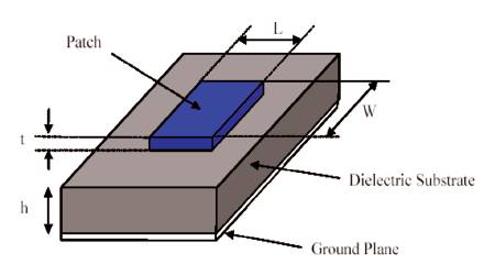
Figure 1. General structure of a microstrip filter
This paper provides knowledge about how to decrease the overall physical size and insertion loss of the filter. Metamaterial is taken as a reference to achieve this goal. Physical size and light weight is a major concern in today's integrated circuit. The application of low pass filter is very wide in the field of communication engineering and the complex receiver in which frequency selection is a primary factor and much more. The rate of change of magnitude with respect to frequency (roll off) and the magnitude in pass band are two most important features of any filters. The particular shape of metamaterial having various unit cell has ability to improve the overall performance of filter. This improves selectivity to great extent. Metamaterial in shape of hexagonal-omega structure provides the negative permittivity.
The field of filter engineering has a history of 80-90 years. Filter is the most important part of all transmitter and receiver section, where selection and rejection of a particular frequency or band of frequency is a major concern. We cannot assume any frequency operated circuit without filter. Different research and development in the field of filter started from 1937. Apart from this, most of the modern concept and theory of filter came into existence during the period of World War II. In the designing of low pass filter the conventional technique is stepped impedance and open stub [1-3]. But the major drawback is that the roll off rate is not very sharp in conventional design of filter. It falls gradually instead of sharply. So the major concern is the rejection characteristics of such filter. To overcome this problem we can sacrifice the pass band characteristics in traditional filter by increasing the number of sections. But due to this method physical size also increases which is not good in PSB and VLSI technology. It is also combatable to Printed Circuit Board (PCB) and MMIC technology [4-7].
One of the many technologies in metamaterial, is the use of Hex-Omega structure [8] in the base of microstrip line to enhance the stop band characteristics and selectivity of microstrip LPF. In the environs of response, the use of metamaterial in the shape of hexagonal structure produce a sharp cutoff. By implementing the hex omega and other different predefined structure at the ground of basic microstrip low pass filter, it is possible to implement and realize a filter which has better pass band characteristics that does not contain much ripples, as well as carry a sharp and steep roll-off rate without compromising on the size of the circuit.
Metamaterial is a man made substance, which has some special characteristics which is not found in other available natural substances. Vassalage explained the theory of metamaterial and said that in metamaterial the direction of phase variation and actual direction of wave (pointing vector) is mutually opposite to each other [9]. He called metamaterial a left hand substance. From last few decades, metamaterial in microstrip technology act as an integral part of many designs.
In the designing of low pass filter, reduced size of low pass filter with better performance is the major concern in the area of microstrip technology. Low profile with improved filter characteristics is intensively investigated in the field of low pass filter with different alternative [10]. Metamaterial (MTM) technology was introduced by a Russian scientist Victor Veselago in 1967. Low pass filter designed and implemented on microstrip transmission line is compact in nature, and accept all the advantage of microstrip technology. Structure form on the patch of microstrip is designed on the basis of several important laws and procedures like transformation from prototype, Richards's transformation, and Kurda's identities. The pass band and stop band characteristics depend upon the mathematical calculation which is done during the design procedure. Length and width of microstrip line are also calculated by some standard formulas and procedures. The physical length actually reflects the characteristics of prototype component parameter value in a LC low pass network. The general structure of microstrip filter is shown in Figure 1. Distance of ports from the main structure boundary play an important role on the performance of low pass filter. Pass band gain, insertion loss, ripples are the main parameters of filter, which can be adjusted by varying the physical size of patch and operating frequency range or both simultaneously, according to application.
Figure 1. General structure of a microstrip filter
In the frequency range of MHz to GHz LC tank resonator circuit provides proper frequency selection. The disadvantage of such lumped filter is low quality factor and large size. Also, as frequency decreases from KHz range to few Hz size inductor becomes bulky. So, low frequency filter is designed using crystal to overcome this problem, which has great frequency stability and exhibit both series and parallel resonance.
In comparison of size and performance, microstrip transmission line and coplanar waveguide (CPG) are also good resonators than lumped element filters. The steps and procedure to make a microstrip circuit is quite similar to manufacturing of PCB. Low pass filter designed using planar technology consist of high quality factor and low loss tangent of dielectric material for substrate.
Bandwidth is basically defined as the range of frequency over which magnitude falls 0.707 times of the maximum magnitude. In this range, signal is approximately the exact replica of input in terms of magnitude. In typical low pass filter, lower 3db cutoff frequency is approximately near to zero.
Using metamaterial it is possible to achieve the negative permeability, negative permittivity and negative refractive index at the same time [11]. Victor Veselago is known as the father of this special material. Characteristics of magnetic and electric field is different in metamaterial as compared to other known conventional substances. Veselago first found that in metamaterial, the value of electric permittivity and magnetic permeability is less than zero (negative) [13]. This field is characterized by the left hand rule. This is the reason that metamaterial is known as left (LH) Metamaterial [12]. Four different states of this is shown in Figure 2. From Figure 2. it is clear that, for the reflection of wave, it is necessary that wave must fall into the plasma from the air. So in metamaterial negative refraction occurs [14]. Veselago explained about the occurrence of metamaterial in his paper work “The electrodynamics of substance with simultaneously negative permittivity and negative permeability”. So now a-days left/right hand material is widely used in transmission line to improve the filter performance [15]. Metamaterial structure having Split Ring Resonators (SRRs) are used to produce negative permeability and thin wire elements are used to to generate negative permittivity. SRR is a novel design consisting of two concentric rings with a split on each ring. The structure is called resonator since it possess a certain magnetic resonance at a particular frequency. Split ring resonators can result in an effective negative permeability over a particular frequency region. The SRR structure is made by two metallic rings having a common center with a split on opposite sides. This acts as an LC resonator with distributed inductance and capacitance that can be energized by a alternating external magnetic field component of the normal direction of resonator.
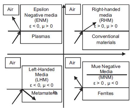
Figure 2. ε-μ Variation
Till now, it is clear that metamaterial contain negative refractive index. It means that it does not follow snell's law, and actually its characteristics is just opposite to snell's law, so it is called material having negative index, which is shown in Figure 3.
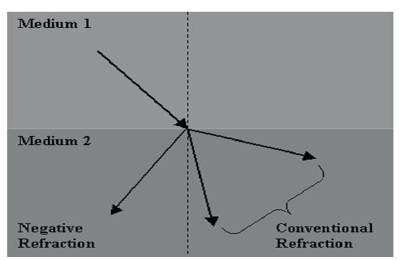
Figure 3. Normal and negative refraction
The effect of negative refractive index is that the direction of group velocity is exactly opposite to that of phase velocity which is also the actual direction of flow of energy [16].
Progressive development in the field of metamaterial can be summarized as-
1967- Theoretically proposed by Vesalogo.
1999- First negative Mu material by Pendry
2000- First Metamaterial by Smith
2003- Transmission approach by Caloz
2009- Miniaturized structures for optical frequency
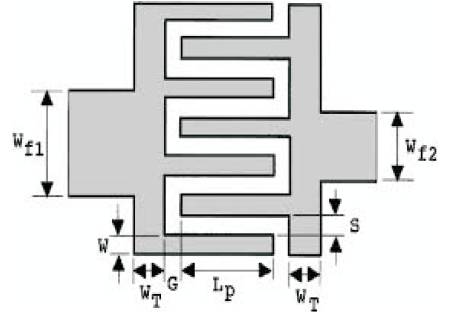
Figure 4. Structure of Interdigital line
Microstrip filter based on composite right/left-handed metamaterial transmission lines have been showed in this work. Also microstrip filter which is based on resonant principle (left handed) is also discussed here. It is demonstrated that metamaterial structure behaves as an effective (continuous) medium with left handed wave propagation in the pass band. It is possible to design a compact planar microstrip filter with the help of metamaterial because of small electrical length of the resonator. At last it is observed that filter designed with metamaerial has significant advantages over conventional microwave filter in terms of size and performance.