Figure 1. Single precision IEEE floating point format
This paper presents the design and comparison of the high speed single precision binary floating point multiplier using IEEE-754 format implemented through the Faster Dadda, Vedic from Dadda and the modified Booth algorithm. The Faster Dadda algorithm utilizes the parallel independent column compression technique and the Hybrid adder. The Vedic from Dadda is the concept of utilizing the Dadda to get higher order multiplier through Vedic concept. Integer multiplication can be inefficient and costly, in time and hardware, depending on the representation of signed numbers. The modified Booth algorithm uses the encoding techniques which minimize the partial products. These single precision Floating point multipliers based on IEEE 754 are implemented using VHDL and they are targeted for Xilinx Spartan-3E FPGA. The performances of these multipliers are analysed in terms of speed, area and area-delay product.
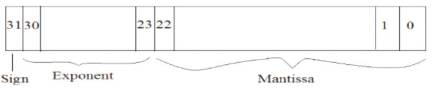
Multiplier is one of the Key hardware blocks in the digital systems. The performance of digital systems can be enhanced with the high speed Multiplication unit. Multiplier units are widely seen in the DSP's and Microprocessors. The DSP Processors most widely use the single precision floating point multipliers to perform its DSP Applications. One of the ways to represent the real numbers in binary format is by floating point numbers. According to IEEE 754 ( The Institute of Electrical and Electronic Engineers Inc. ), the floating point numbers are represented in two formats – Binary interchange format and Decimal interchange format. The single precision Binary interchange format is chosen to implement the design. The single precision format has 32bits as shown in Figure 1. The MSB bit indicates the Sign field (S), the exponent field (E) and has 8 bits which is biased to 127 and the mantissa field has 23 bits. An extra bit is appended to the mantissa field, called Significand if the exponent is greater than 0 and smaller than 255. The presence of Significand, implies that the number is normalized.
Figure 1. Single precision IEEE floating point format
Where, bias = 127, the Mantissa (M) is given by
Floating point Multipliers provide high accuracy in performing the operations, so it is adopted in various areas. An efficient Implementation of IEEE 754, Single precision Floating point Multiplier unit is designed using Xilinx Spartan 3E FPGA ( Mike Field, pp. 12 to 18) and verified. The Floating point Multiplier unit is designed using the Pipelining feature which enhances its performance. Synthesis and simulation results are obtained using the Xilinx 14.5 platform.
In the Floating point Multiplication, the computational time is taken by the Sign generation, and time taken for Exponent evaluation is not more than that for Significand Multiplication. So, the Significand Multiplication should be highly efficient and effective. The adoption of the right algorithm for the Multiplier unit plays a vital role in deciding its computational speed. The Pipelining feature is enabled for this Multiplier at various stages which can enhance the performance of the Multiplier.
In Column compression, Multipliers have gained popularity because of their High-computational speed. Wallace and Dadda Multipliers are renowned Column compression Multipliers. The Wallace Multiplier was proposed by Chris Wallace, an Australian computer scientist in 1964. The Dadda Multiplier was proposed by Luigi Dadda, an Italian Computer Engineer by altering the Wallace Multiplier. The Wallace and Dadda Multipliers are reduction based Multipliers. The reduction is achieved by compressing the columns with a [3,2] counter (Full adder) and a [2,2] counter (Half adder). The three stages that are involved in both Wallace and Dadda Multipliers are similar.
In Wallace Multiplier ( C.S. Wallace, pp. 14 to 17) the reductions are done as much as possible in the layer but in Dadda ( L.Dadda, pp. 349 to 356), only few reductions are done. Thus, due to above reason, the number of [2,2] counters required for Wallace Multiplier is quite high. But the Dadda Multiplier does not require many [2,2] counters like Wallace. When a comparison is carried out between them ( Whitney J. Townsend , J.A. Abraham and Earl E. Swartzlander, pp. 552 to 560 ), the Dadda Multiplier requires less hardware than the Wallace. Also, the Dadda Multiplier is slightly faster in computation than Wallace. This made the Dadda Multiplier to be more focused in the implementation.
Vedic multiplier ( AniruddhaKanhe, Shishir Kumar Das, Ankit Kumar Singh ) is based on the algorithm, called Urdhva Tiryagbhyam, which is one of the 16 Vedic Sutras. Urdhva refers to vertical and the Tiryagbhyam refers to the crosswise. This Sutra specifies how to handle the n*n order multiplication by smaller order multipliers. The first basic multiplier block required for the implementation of Vedic multiplication is the 2*2 multiplier. From this basic 2*2 multiplier the 4*4, 8*8, 16*16, 32*32 are developed. The Vedic from Dadda technique is very similar to the Vedic concept, the main change here is, instead of a basic 2*2 multiplier a Dadda reduced 8*8 multiplier is adopted.
Andrew Donald Booth proposed Booth's multiplication algorithm which can perform the multiplication operation of Two Signed Binary numbers in their respective 2's complement form. A.D. Booth's encoding technique is also called Radix-2 Booth's encoding algorithm. Later, the modified Booth Algorithm's evolved. These modified Booth Algorithms exist in radix-4 and radix-8 form. The Multiplier in the modified Booth Algorithm uses the recoding Technique. This recoding technique reduces the number of partial products, so that the addition process becomes simpler.
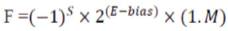
The Single precision Binary Floating point of the IEEE 754 is normalized by appending an extra bit in its MSB to Mantissa, called Significand. The normalized floating point numbers have the form
The Multiplication of these floating points can be done with the following Algorithm.
1. Multiply the 24-bit Significands, i.e. (1.M1 x M2 )
2. Place the decimal point in the result.
3. Evaluate the exponent part, i.e. (E1 +E 2- bias)
4. Generate the sign part, i.e.(S1 XOR S2 )
5. Normalize the result, i.e. to obtain 1 at the MSB in the Significand of the result
6. Round the extra bits in the result from LSB.
7. Check for Underflow/Overflow occurrences.
Consider the single precision floating point numbers as IEEE 754, but with mantissa part restricted to only 5 bits. Consider, two floating point numbers
A = +17
B = - 8.5
Normalized - Binary form of A & B
A = + 1.0001*24
B = - 1.0001*23
The Mantissa part is restricted to only 5 bits.
A = 0 10000011 00010
B = 1 10000010 00010
1. Multiplication of Significands
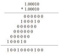
2. Placement of the decimal in result
1.0010000100
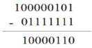
3. Evaluation of the exponent part
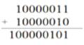
The exponent that results in the above has the two bias's added into it.
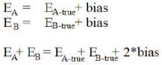
The true exponent is obtained by subtracting the extra bias from the above exponent.
4. Generation of the Sign bit:
0 XOR 1 = 1(negative)
5. Normalization of the result is done by having 1 before the decimal point. During this process, when the decimal is shifted to left, the exponent part increments by shift times. Similarly, when shifted to right, the exponent part decrements by shift times. 1 10000110 1.0010000100
In the above case the normalization is not required.
The result (de-normalized):
1 10000110 .0010000100
6. Rounding the extra bits in the result from LSB to only 5 bits.
1 10000110 0010000100
The Rounded result is:
1 10000110 00100
The architecture of the floating point multiplier is shown in Figure 2 which shows the independent blocks - sign generation, exponent evaluation and the Significand multiplication. These blocks are executed in parallel.
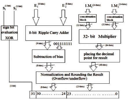
Figure 2. Architecture of Floating point Multiplier
The Significand which is a 24-bit is concatenated with 8 zeros in the MSB position to form a 32-bit binary number. These 32-bit binary numbers are multiplied with the help of a 32-bit Multiplier. The result obtained from the 32-bit th Multiplier is a 64-bit. Decimal point is placed at the 46 position in the result. The exponents are added with the help of an 8-bit Ripple Carry Adder. The 9-bit result obtained from the RCA is not the true exponent. On subtracting the extra bias from the 9-bit result, then the 8- bit true exponent is seen. Exponent and Significand result is normalized with the Normalization unit. Finally the Mantissa result is rounded to a 23-bit by removing the extra bits from its LSB position.
The MSB in the Single precision Floating Point number gives the Sign. On multiplying two numbers, the sign of the result varies. The 0 represents the number as positive and the 1 represents the number as negative. On multiplying either two negative numbers or two positive numbers the result is positive. When a negative number is multiplied to a positive then the result sticks to negative.
Figure 3 represents the sign generator block which uses the XOR logic gate for generating the Sign. Table 1 gives the illustration of XOR logic.
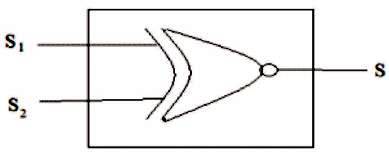
Figure 3. Sign Generator block (XOR)
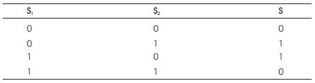
Table 1. Sign bit Generation (XOR)
The exponent evaluation is performed with the help of an 8-bit Ripple Carry Adder. In this design, most of the computational time is spent in the Significant multiplication process, so there is no need for faster addition. The speed of the multiplier can be enhanced with a faster Significant multiplier and for exponent addition a moderate adder is sufficient. As shown in Figure 4 the RCA utilizes one Half Adder to calculate the LSB part S . The carry bit from one adder propagates through 0 successive Adders. All the rest of the bits are evaluated with the help of 7- Full Adders. The result obtained from the 8-bit RCA can be a 9-bit. This result doesn't imply the true exponent.
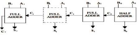
Figure 4. 8-bit Ripple Carry Adder
The true exponent is obtained by subtracting the bias 12710 i.e. 0011111112 from the result. As shown in Figure 5 it requires a 7 – One Subtractors and 2 - Zero Subtractors.
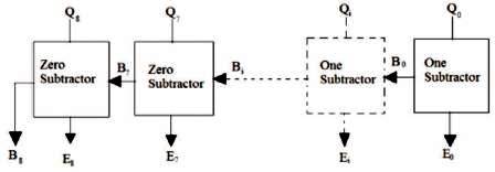
Figure 5. Ripple Borrow Subtractor
The One Subtractor shown in Figure 6, which subtracts the bit '1' from the input bit producing an output and a borrow to next stage. So also, the Zero Subtractor shown in Figure 7 subtracts the bit '0' from the input bit producing an output and a borrow to the next stage.
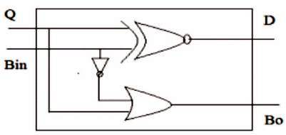
Figure 6. One Subtractor
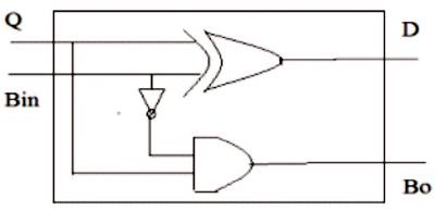
Figure 7. Zero Subtractor
In the Multiplication of Single precision Floating point numbers, an effective and efficient multiplier reduces the computational time. The 24-bit Significand Multiplication is achieved through formation of a 32-bit binary number by concatenating 8 zero's in the MSB. Thus, a 32-bit Multiplier is developed with following algorithms:
Dadda proposed a method of reduction which achieves the reduced two-rowed partial products in a minimum number of reduction stages. Dadda succeeded at this, by placing the [3,2] and [2,2] counters in maximum Critical path in an optimal manner. For N-bit multiplier and multiplicand, the results is a N by N partial product. These partial products are arranged in the form a Matrix. Dadda reduced the Matrix height to a two-rowed matrix, through a sequence in the reduction stages.
The Algorithm for Dadda is:
1. Let us assume that the final two-rowed matrix height is d1=2. Based on d1 the successive matrix heights are obtained from dj+1 = 1.5 * dj, where j = 1,2,3,4,............, Rounding of fraction in this matrix height should be done down to least. i.e, 13.5 = 13(rounded). The matrix heights will be in this fashion 2,3,4,6,9,13,19,28............. Finally the largest dj should be obtained such that the height of the derived matrix should not exceed the Matrix overall height.
2. In the first reduction stage, the column compression is to be carried with the [3,2] and [2,2] counters such that the height of the matrix obtained should not exceed dj.
3. During the compression, the sum is to be passed to same column in the next reduction stage and the carry is to be passed to the next column.
4. The above two steps are to be repeated until a final two-rowed reduced matrix is obtained.
The Computational speed of the Dadda Multiplier can be enhanced by partitioning the Partial products as shown in Figure 8 which is called Faster Dadda ( B. Ramkumar, V. Sreedeep and Harish M Kittur, member IEEE ).
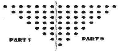
Figure 8. Partitioning of Partial products
Here, the two parts are reduced in parallel with the same Dadda reduction procedure as stated above. Due to this parallelism approach of reduction, the Multiplier is very fast when compared to the custom Dadda Multiplier.
The Part 0 Matrix compression (Figure 9) takes 17 - [3,2] counters and 6 - [2,2] counters to get final two-rowed Matrix. The final stage is merged with the Carry propagation adder and an 11-bit result is obtained.
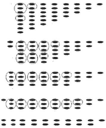
Figure 9. Part0 reduction
The Part 1 Matrix compression in Figure 10 takes 14 - [3,2] counters and 5 - [2,2] counters to get final two-rowed Matrix. The final stage is merged with the Carry propagation adder and an 8-bit result is obtained.

Figure 10. Part 1 reduction
As shown in Figure 11 the first 9 bits in part 0's result is directly carried to the final result (p(0) to p(7)). The Common result part in both part 0 & 1 is added with 3-bit RCA and carried to final result (p(8) to p(10)). Also, the final result part from p(11) to p(15) is obtained through the Hybrid Adder shown in Figure 12. Thus, a 16-bit result is obtained.
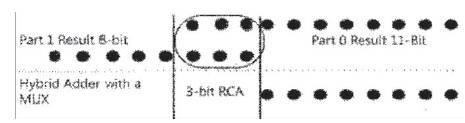
Figure 11. Merging the results from part 0 & 1
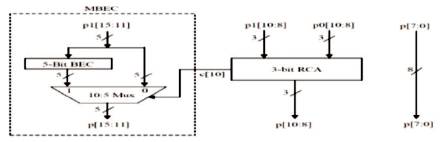
Figure 12. Hybrid Adder
The Hybrid adder part has a 10:5 Mux which selects the final result part p(11) to p(15) based on the carry from its successive 3-bit RCA. When the carry bit is 1, the 5-bit Binary to Excess-1 Code obtained from the circuit shown in Figure 13, is assigned to p(11) to p(15) else the p1(11) to p1(15) is directly assigned to p(11) to p(15). The Hybrid Final adder required for 16-bit Multiplier is shown in Figure 14. Similarly, the hybrid adder required for 32-bit Multiplier is shown in Figure 15.
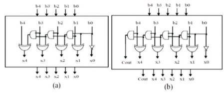
Figure 13. The 5-bit Binary to Execss-1 Code Converter: (a) BEC (without carry), (b) BECWC (with carry)
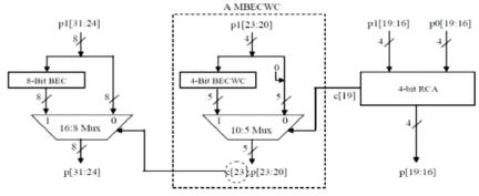
Figure 14. Hybrid Final Adder for 16-bit Multiplier
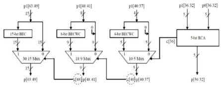
Figure 15. Hybrid Final Adder for 32-bit Multiplier
Vedic mathematics is the ancient Indian system of th mathematics. It was rediscovered in the early 20 century. We know that a Multiplier is a key hardware block in the architecture of either DSP's or microprocessor which defines its speed and power. The multiplier implemented through this Vedic technique ( Poornima M, Shivaraj Kumar Patil, Shivukumar ,Shridhar K P, Sanjay H ) gives the good results in terms of speed and power considerations. All ancient Indian mathematical works were composed in Sanskrit, and usually consisted of a section of Sutras. The Vedic mathematics uses simple rules and principles to solve problems in arithmetic, algebra, trigonometry and geometry.
This Vedic system is based on 16 Vedic sutras. Here, the natural ways of solving the problems is adopted on which human minds work more effectively. These Vedic systems have the effective algorithms.
The Vedic from Dadda Algorithm is implemented by using the Direct Dadda 8-bit Multiplier as the basic building block. From a 8-bit Dadda multiplier, a 32-bit multiplier can be obtained by constructing a 16-bit multiplier first through Vedic concept. Then using that 16-bit multiplier, the 32-bit multiplier is then obtained.
In this, first a Direct 8-bit Dadda Multiplier is developed. The 16-bit Multiplier is developed using Direct 8-bit Dadda through Vedic, as shown in Figure 16.
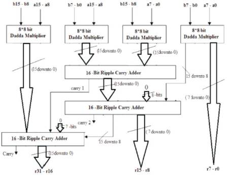
Figure 16. A 16-bit Multiplier from 8-bit Direct Dadda
Using the above 16-bit multiplier through Vedic, a 32-bit multiplier is developed as shown in Figure 17
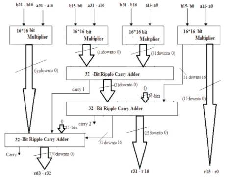
Figure 17. A 32-bit Multiplier from 16-bit Multipliers
Booth’s multiplication or Radix-2 algorithm is proposed by A.D. Booth, which can perform the multiplication operation of Two Signed Binary numbers in their respective 2's complement form. ( SandeepShrivastava, Jaikaran Singh, MukeshTiwari ).
The Radix-2 Booth's Algorithm is as follows:
1. Binary Number with least number of transitions (0 to 1 or 1 to 0) is selected as Multiplier and with more number of transitions is selected as Multiplicand. In the above 1100 has only one transition (1 to 0) so it is chosen as Multiplier whereas the 0010 has two possible transitions(0 to 1 & 1 to 0) so it chosen as Multiplicand.
2. Now, Multiplier X = 1100 and Multiplicand Y = 0010, the two's compliment of Y is denoted as ' -Y ' = 1110.
3. Initialize the AC = 0,X-1 = 0,then compare the LSB X0 and X-1, when' 00 'or '11' Perform Arithmetic shit operation only, when' 01 'add Multiplicand(Y) to AC or when' 10 'subtract Multiplicand(Y) from AC.
4. The Multiplication is illustrated in Table 2.
5. The Result is 11111000 which is ' -8 '.
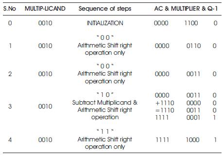
Table 2. Booth Multiplication of X=1100 & Y=0010
In this algorithm, the Yi and Yi-1 bits of the multiplier are examined and then recoding is done as shown in Table 3. Booth Recoding reduces the number of partial products which can reduce the hardware and improve the speed of the operation. Some considerable delay is seen during the generation of partial products. This radix-2 Booth recoding works well with serial multiplication which can tolerate variable latency operations with minimum number of serial additions. In case of parallel multiplication the worst case is seen. The worst case is a nbit Multiplicand that significantly requires ‘n’ - number of additions. Here the number of partial products seen are also ' n '.
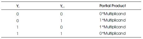
Table 3. Radix-2 Booth recoding
In the Radix-4 ( S. Shrivastava, P. Gulhane (2014) ), the grouping of multiplier bits for recoding is done with 3-bits taken at a time. The first group is formed by taking the first bit as zero and the remaining two bits are the two LSB bits of Multiplier. When forming the Second group, the first bit is considered as the MSB bit of first group and remaining two bits are from the multiplier. This repeats for next group formation also. The Booth Radix-4 algorithm reduces the number of Partial products by half at minimum circuit complexity with the help of Table 4. This Radix-4 can also be called as Modified Booth Algorithm. Booth recoding is carry free and is completely performed parallel to have speed. The Radix-4 Booth recoding works effectively for both Signed and Unsigned numbers.
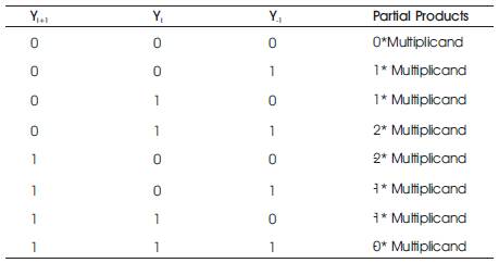
Table 4. Radix-4 Booth recoding
The Algorithm for radix-4 Booth recoding is as follows:
1. The Least Significant Bit (LSB) should be padded with zero (Y-1 = 0 )
2. For Signed, the MSB must be padded with two zeros when n is even or else one zero. For Unsigned, the padding is not necessary when n is even.
3. Grouping of Multiplier into 3-bits must be done which in turn are overlapping.
4. Partial products are generated with the help of Booth's recoding table as stated above.
5. On adding the partial products the result can be found.
In this Booth's Radix-4 Multiplication, the partial products are reduced to n/2. Here, Y is the Multiplier which is encoded with the circuit as shown in Figure 19. X is Multiplicand. Y2j-1, Y2j, Y2j+1 are the three alternatively Grouped bits which are encoded to {0, X, 2X, -X, -2X}. In the circuit shown in Figure 18 the NEG specifies the sign for X or 2X.
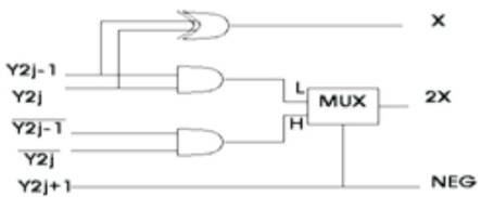
Figure 18. Booth's radix-4 Encoder
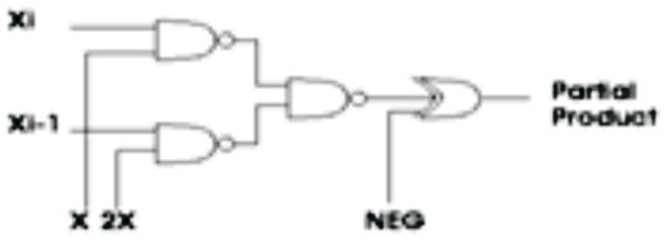
Figure 19. Partial product Generator
Now, the Partial products are generated with the help of the circuit shown in Figure 19. Xi Xi-1 are the Multiplicand bits. As specified by the X, 2X, NEG the partial products are generated.
The result of the Significand Multiplication may or may not be a normalized one. A normalized result has the leading bit '1' which is immediately followed by the decimal point. Since, the inputs are normalized numbers, the result from Significand Multiplication has the leading one at bit 46 or 47.
1. When there is one to the immediate left of decimal point at bit 46, it doesn't require any Shift operation.
2. When there is one at bit 47, it requires right Shift and exponent is to be incremented by one.
The Shift operations are performed by the Combinational Shift logic circuits which uses the Multiplexers.
Overflow occurs when two exponents are added or during the normalization. The result from the exponent evaluation unit must be 8 bits. Overflow which occurrs during exponent evaluation can be compensated by subtraction of bias. The underflow which results during this subtraction can never be compensated. If the final exponent after subtraction is 0 then during normalization it is compensated by addition of 1. Table 5 shows the effect of normalization on the result from exponent evaluation unit.
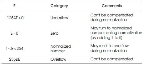
Table 5. Effect of Normalization On The Result From Exponent Evaluation Unit And Overflow/underflow Detection
The Multiplier units developed using all the above three algorithm's was designed in VHDL and simulated using Isim. This ISim is the ISE Simulator which provides a complete full-featured HDL Simulator integrated within ISE. The design was synthesized using Xilinx ISE 14.5 tool targeting the Xilinx Spartan 3E family of device type xc3s500e-5fg320 FPGA
The Test bench is written for all the three multipliers which is used for stimulus generation. This is applied to all the three implemented Floating point multipliers. The results obtained for all the three multipliers were compared.
The Simulation results for the corresponding inputs are shown in Figure 20 which was similar in all the multipliers developed by the three specified algorithms. The Simulation is done using the Xilinx 14.5. Here, the following Floating point numbers which are represented in hexadecimal are considered for simulation on ISim targeted to Spartan 3E family FPGA.
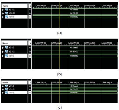
Figure 20. Simulation results for various multipliers (a) Dadda Algorithm (b) Dadda using Vedic Mathematics (c) Booth Multiplier
Single precision Floating point Multiplicand and Multiplier are: (in 32bit Hexadecimal)
a = 4015eeab
b = 8c150400
Result is: r = 8cae8c82
The RTL Schematic is shown in Figure 21 for the Multiplier in which the Significand multiplier (32bit Direct Dadda) is developed by Faster Dadda algorithm. The RTL Schematic is shown in Figure 22 for the Multiplier in which the Significand multiplier (8bit Direct Dadda) is developed by Vedic from Dadda algorithm. Similarly, the RTL Schematic is shown in Figure 23 for the Multiplier in which the Significand multiplier (32bit Booth) is developed by Booth algorithm. The results from various multiplication algorithms in terms of area, speed and area-delay product are presented in Table 6.
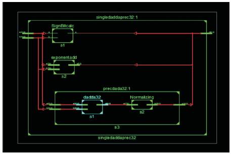
Figure 21. RTL Schematic for 32bit Direct Dadda Multiplier
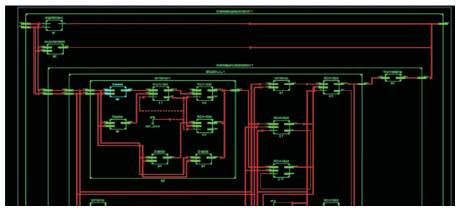
Figure 22. RTL Schematic for 32bit Multiplier from 8bit

Figure 23. RTL Schematic for 32bit Booth Multiplier
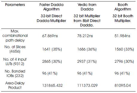
Table 6. Comparison Results
In this paper, the Single precision Floating point multiplier architecture has been implemented with three different Multiplication Algorithms. The Multiplier architecture developed from booth algorithm has better efficiency as regards the area and delay when compared to Faster Dadda Algorithm and Vedic from Dadda Algorithms. The area-delay product of the Multiplier Architecture developed by modified Booth Algorithm is 27.17% lesser than Vedic from Dadda and 38.50% lesser than Faster Dadda based architecture. Further, it is possible to implement double precision floating point multiplier to get better efficiency when compared to previous algorithms.