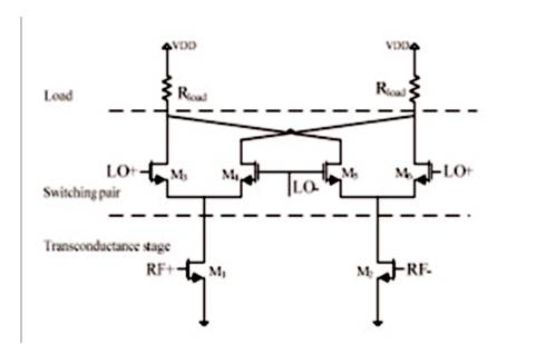
Figure 1. Conventional CMOS Gilbert cell
This paper presents a broadband low noise mixer based on a double balanced Gilbert cell that works between 1-6 GHz. One of the most important factors of the mixer noise figure is flicker noise. All transistors in this design are biased in the subthreshold region in order to suppress mixer noise figure. Also dynamic current injection circuit (current bleeding circuit) has been utilized to improve the noise performance. Shunt peaking technique is adopted to have a flat conversion gain. The simulation results of the designed mixer show 21.1 dB conversion gain and 6.41 dB average noise figure at 1 GHz - 6 GHz. Also simulation results demonstrate that, using current bleeding circuit, low noise figure is obtained . Its consumption power is 10.6 mW at 1.8V supply voltage. The noise figure is an important parameter to be considered in the design of Gilbert cell mixer and is further improved using the proposed method. A dynamic current injection technique with a tuning inductor has been employed in the mixer design in order to reduce the output noise corner frequency. The traditional Gilbert based wideband active mixers realized by pure bipolar and MOSFET have been demonstrated in recent years.
Recently, various high-speed wireless standards such as GSM, Wi-Fi, and GPS have been developed. To satisfy the specific demands for each application, it is straightforward to integrate different wireless receivers together on a chip [1]. Narrowband receivers cannot meet our needs, and it increases the design difficulty comparing with narrowband receiver [2]. So, more multiband multi-standard devices are becoming available [3]. The mixer is an important building block of a receiver [4]. With a broadband low noise mixer, the design of a multiband multi-standard receiver can be much simplified [3]. The double balanced Gilbert cell mixer is widely used as the down converter in CMOS receivers [5] . Then noise figure is an important parameter to be considered in the design of Gilbert cell mixer [6]. High noise figure of the mixer degrades the entire receiver performance [7]. In recent years, several techniques have been described to decrease flicker noise which is a primary factor to enhance the noise figure of the conventional Gilbert-type mixers. Due to the concept of the current reuse bleeding technique, which was proposed by MacEachern [8], it has become one of the most commonly used topology for reducing noise. Recently, the current-reuse bleeding technique with two resonating inductors was proposed in [9], which exhibits improvement in noise performance compared to the conventional current-reuse bleeding technique [10] .
A dynamic current injection technique with a tuning inductor has been employed in the mixer design in order to reduce the output 1/f noise corner frequency. Tuning inductor is used in the mixer circuit to cancel out the effect of the parasitic capacitor between the LO switches and RF trans-conductance stage [11]. However, the bipolar mixer has very good noise and gain performance, but relatively poor linearity. The MOSFET version can achieve the best linearity, but very poor noise and gain capability [12]. In this paper, for the purpose of expressing the advantages of sub-threshold mixer, the author has designed a 2.4 GHz CMOS active mixer. The remainder of the paper is organized as follows; section 1 explains the preliminary analysis of Gilbert cell mixer; section 2 introduces the proposed sub-threshold mixer; the simulation results are presented and compared with conventional Gilbert cell mixer in Section 3 and finally the conclusion is given.
A conventional double-balanced Gilbert cell as shown in Figure 1 is composed of trans-conductance stage, switching pairs, and output load stage [23]. The basic mixer carry on the frequency translation by multiplying the RF input signal with a LO input signal, which varies from 1 to 6GHz, to produce the IF output signal in the low frequency [13]. The transconductance transistors, MI and M2, transform RF voltage amplified by LNA into drain current. Down-converted by the switch quad comprising M3-M6, IF current is transformed back to voltage through the load [14].
Figure 1. Conventional CMOS Gilbert cell
Flicker noise is one of the critical issues in a DCR mixer which is caused by each stage of trans-conductance, switching, and output load. Transconductance FETs only contribute white noise after frequency translation, since the flicker corner frequency of these devices is usually much lower than the LO frequency [15]. Regarding the load, a poly resistor load (RL), which is free from flicker noise, has been used in the proposed mixer. The flicker noise performances of the mixer are primarily determined by LO switching pair devices [16]. The flicker noise introduced by the switch quad is described into two mechanisms. One is direct switch noise caused by samples of switch flicker noise at twice the LO frequency during the on and off transit aperture. The other is the indirect switch noise introduced by charging and discharging of the parasitic capacitance Cp, by the flicker noise at 2fLO [15]. Output flicker noise current by the direct and indirect mechanisms are described as:


Where T is LO period, Vn is the equivalent flicker noise of the switching pairs, and S is the slope of the LO signal. Also, Weff Leff are the effective width and length, Cox is the oxide capacitance, f is frequency, and Kf is a process parameter. From equation (3), Vn is inversely proportional to the WL of the device equation [9]. From equation (1), To minimize the low-frequency noise appearing directly at the output, it is preferable to reduce the Idc and increase the size of the switching pairs, but large switches increase the parasitic tail capacitance at the node between the switches and the RF transconductance stage (see Figure 1), which leads to a larger contribution of the indirect noise at the output [17].The static current bleeding technique is implemented by using two PMOSFETs to reduce the bias current of the LO switches. From equation (1), if the bias current of the LO switches is decreased, the output flickernoise current generated by the direct mechanism can be minimized [18]. In addition, RF leakage current flows through the injection circuit, which decreases conversion gain and also allows more RF current to be shunted by the tail capacitance (Cp ) at the node between the LO switches and RF transconductance stage [16]. To solve this problem, Dynamic current injection (DCI) was proposed. It injects a dynamic current equal to the bias current of each pair at only the LO switching event [5] .
Different from that in narrow band mixer, the input RF signal of mixer used in UWB system occupies a significant amount of bandwidth. Therefore, the bandwidth of the mixer should be large enough to keep the conversion gain flat in such a wide bandwidth [19]. Two series inductors are placed between the RF input stage and the switching stage. The analysis of the resonated inductors is shown in Figure 2. When one of the switches is on, the mixer can be approximated by a voltage-control current source. CP is the total parasitic capacitance at the source of the switching stage. The RLC network decreases the rising time of the parasitic capacitance [20]. At t=0, there is a sudden step change in the current source. The high impedance of the inductor decouples the resistor from the capacitor, which means all the current goes into charging the capacitor [3]. So, in this way, the rising time decreases and the bandwidth increases.
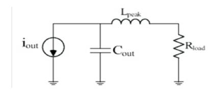
Figure 2. Resonated inductors network analysis
Dynamic Current Injection (DCI) was originally proposed in [5] to reduce the flicker noise and applied in many mixers. It has excellent flicker noise performance, but linearity is the same as a conventional mixer. As shown in Figure 3, three PMOS transistors, M7-9 were used to inject a dynamic current equal to the bias current of each pair of switches at only the switching event [17]. The PMOS devices, M7-8, must be sized properly to turn ON and OFF at each zero-crossing, yet do not add significant parasitic capacitance at the common source of the switches [5] .
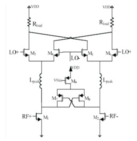
Figure 3. Proposed sub-threshold mixer
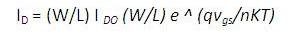
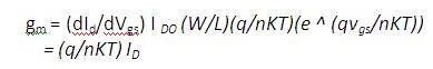
Sub-threshold CMOS circuits behave differently if compared to the strong inversion CMOS circuits; they become more sensitive to voltage supply variations, temperature variations, and process parameter variations. However, they have some favorable characteristics such as increased transconductance gain, due to the exponential relationship between the voltage and the current as seen in equation (4,5), and near ideal static noise margin [21].
There is another benefit to operating the mixer transistors in weak inversion. Assuming constant gm in the transistors, the noise performance will be improved significantly in weak inversion when compared to an implementation using devices in strong inversion. Flicker noise is inversely proportional to device size, and a weakly inverted device will be considerably larger than a strongly inverted device with identical gm. In addition, the thermal noise will be reduced because the value of the drain thermal noise factor, will be approximately 25% smaller in weak inversion [22].
The proposed mixer is simulated in TSMC 0.18μm RF CMOS technology is shown in Figure 3. The mixer draws 5.9mA from 1.8V power supply. The mixer operation bandwidth is between 1-6 GHz with RF frequency of 2.4 GHz and LO frequency of 2.3 GHz. For comparative purpose, the conventional Gilbert type mixer has been designed entirely the same as the proposed mixer, except current bleeding circuit and inductors. Figure 4 illustrates a comparison between the conversion gains of two mixers versus the RF frequency varying from 1 to 6 GHz. The simulated gain at 1 GHZ is 22.5dB and at 6 GHZ is 19.8 dB with an average of 21.1 dB. The peaking inductor performance in achieving gain roll is shown in Figure 5. By adopting two inductors in the proposed circuit, Conversion gain increased more than 1dB. Figure 6 shows drain current of LO switch cell in different topologies. As shown, waveforms become sharpened using current bleeding current. Size of PMOS is very important for the circuit to work accurately. The results of the mixers noise figure are shown in Figure 7. The NF of the proposed mixer is about 5db lower than the conventional mixer. The noise is relatively flat for the proposed mixer with an average value of 6.41 dB. In ranging from 1-6 Ghz, noise varies from 5.44 dB to 7.63 dB. As shown, better result has been achieved using dynamic current injection technique. Table 1 shows the performance comparison of proposed mixer with several designs reported in previous literatures.
Figures 4-7 and Table 1 clearly show the different simulation results and comparison of the mixers.
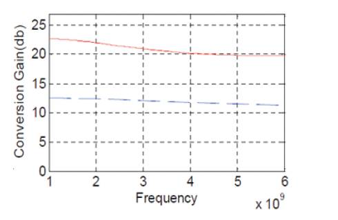
Figure 4. Comparison of CG for two topologies of the mixers; Solid line (proposed mixer), dashed line (conventional)
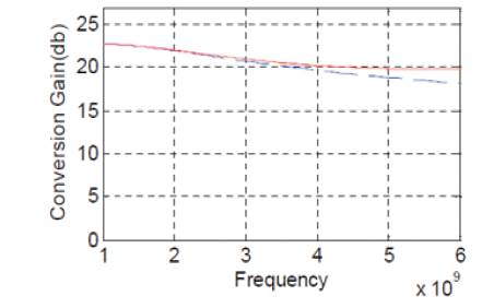
Figure 5. Comparison of CG for two topologies of The mixers; Solid line (proposed mixer), dashed line (conventional)
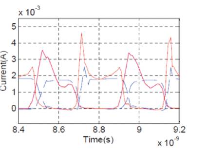
Figure 6. Comparison of drain current of LO switch cell for two topologies of the mixers; Solid line (proposed mixer), dashed line (conventional)
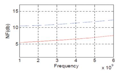
Figure 7. Comparison of NF for two topologies of the mixers; Solid line (proposed mixer), dashed line (conventional
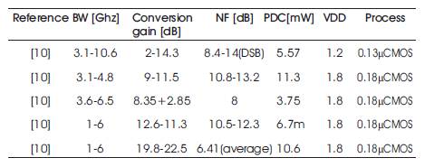
Table 1. Comparison of Mixers
A sub-threshold mixer using dynamic current injection technique and peaking inductor has been proposed and analyzed to improve noise performance. The proposed mixers are designed based on reducing noise of each transistor and decreasing the bias current of LO switches. Results show that the proposed sub-threshold mixer has a good performance on conversion gain and noise figure. A dynamic current injection technique with a tuning inductor is employed in the mixer design and hence reduces the output noise corner frequency.