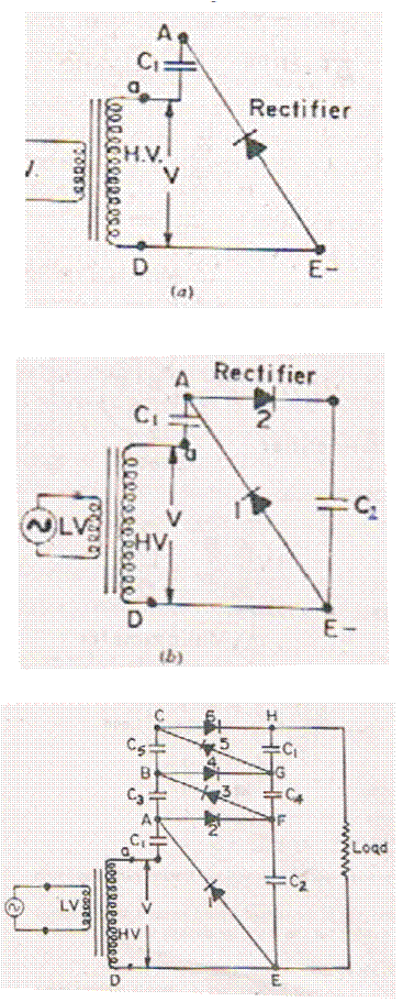
Figure 1. (a,b&c)1. Figures taken from "A course in Electrical and Electronic Measurements and Instrumentation' by" A. K Sawhney
A particle accelerator is a device that uses electromagnetic fields to propel charged particles to high speeds and to contain them in well-defined beams. There are two basic classes of accelerators, known as electrostatic and oscillating field accelerators. Electrostatic accelerators use static electric fields to accelerate particles. An example of this class is the Cockcroft–Walton generator. The high voltage generator of the Cockcroft-Walton accelerator is a well known cascade generator or voltage multiplier circuit. By using only capacitors and diodes, it can step up relatively low voltages to extremely high values, while at the same time being far lighter and cheaper than transformers. The first accelerator of this type was built in 1932 by J.D. Cockcroft and E.T. Walton. They achieved a high voltage of about 700 kV and they studied the first nuclear reaction with an accelerator. They shared the Nobel Prize in physics for 1951. The Cockcroft-Walton generator is discussed in this paper.
A popular way of generating high voltage at relatively low current is the classic multistage diode/capacitor voltage multipler, known as Cockcroft Walton multiplier, named after John Douglas Cockcroft and Ernest Thomas Sinton Walton who used this circuit design to perform the first nuclear disintegration in 1932. This research on voltage multiplier cascade made them winners of the 1951 Nobel Prize in physics for "Transmutation of atomic nuclei by artificially accelerated atomic particles". Less known is the fact that the circuit was first discovered much earlier, in 1919, by Heinrich Greinacher, a Swiss physicist. For this reason, this doubler cascade is sometimes also referred to as the Greinacher multiplier.
The Cockcroft Walton or Greinacher design is based on the Half-Wave Series Multiplier, or voltage doubler. Unlike transformers this method eliminates the requirement for the heavy core and the bulk of insulation/potting required. The biggest advantage of such circuit is that the voltage across each stage of this cascade, is only equal to twice the peak input voltage, so it has the advantage of requiring relatively low cost components and being easy to insulate. One can also tap the output from any stage, like a multitapped transformer. They have various practical applications and find their way in laser systems, CRT tubes, hv power supplies, LCD backlighting, power supplies, x-ray systems, travelling wave tubes, ion pumps, electrostatic systems, air ionisers, particle accelerators, copy machines, scientific instrumentation, oscilloscopes, and many other applications that utilize high voltage DC.
A particle accelerator is a machine that accelerates particles to extremely high energies. These particles are elementary particles like electrons or protons, or - in special experiments - even whole atoms (heavy ions). In modern accelerators the particles very quickly reach almost the speed of light, which is about one billion km/h (to be exact, 1,079,252,848.8 km/h or 299,792.458 km/s). Physicists use particle accelerators to study the nature of matter and energy. The massive machines accelerate charged particles (ions) through an electric field in a hollow, evacuated tube, eventually colliding each ion with a stationary target or another moving particle. Scientists analyze the results of the collisions, attempting to probe the interactions governing the subatomic world. The collision point is usually located in a bubble chamber, a device that records the tracks of ionizing particles as rows of tiny bubbles in a liquid-filled chamber. The paths of the accelerating particles may be straight, spiral, or circular. Although smashing particles may initially appear to be an odd technique of studying them, particle accelerators have enabled scientists to learn more about the subatomic world than any other device. These are devices used to accelerate charged elementary particles or ions to high energies. Particle accelerators today are some of the largest and most expensive instruments used by physicists. They all have the same three basic parts:
Charged particles can be accelerated by an electrostatic field. For example, by placing electrodes with a large potential difference at each end of an evacuated tube, British scientists John D. Cockcroft and Ernest Walton were able to accelerate protons to 250,000 eV. Another electrostatic accelerator is the Van de Graaff accelerator, which was developed in the early1930s by the American physicist Robert Jemison Van de Graaff.
Let us consider the circuit of Figure 1(a). The diode charges the capacitor C1 to a voltage +Vm where Vm is the peak voltage on high voltage(H.V) side of the high voltage transformer.

Figure 1. (a,b&c)1. Figures taken from "A course in Electrical and Electronic Measurements and Instrumentation' by" A. K Sawhney
The voltage at the end 'a' varies between +Vm and -Vm with respect to earth(E) and so the voltage at the point A oscillates between 0 and +2Vm with respect to E. Let us consider the circuit of Figure 1(b). Here the capacitor C2 is charged to a voltage +2Vm through diode2. The Cock-Croft-Walton circuit is shown in Figure 1(c). It is a cascade connection. The potential of A varies between 0 and +2Vm, thus at point F,. there is a steady potential of +2Vm. The voltage applied to capacitor C3 via diode if C3 were unchanged would vary between 0 and +2Vm. Thus C3 charges upto the peak voltage i.e. +2Vm. The voltage at the point B oscillates between +2Vm and +4Vm. This gives a voltage of +2Vm across C4, as F is already at +2Vm. Thus C4 charges to a steady potential of +2Vm. The potential of G with respect to earth becomes +4Vm. The portion BCHG is the 3rd stage of the circuit. The output of the whole circuit is +6Vm. For an n stage circuit, the output voltage is +2nVm. Thus, if we go on adding stages, we can obtain higher and higher voltages.
Here are some applications of the Cockcroft-Walton voltage doubler circuit for generating high voltages from a low voltage AC source. The circuit is quite practical for generating thousands of volts (or more) or just a few volts at high current. Since the circuit is AC-coupled it may be connected to a power supply's secondary transformer winding to generate an additional or opposite polarity voltage.

Figure 2. Typical Photomultiplier Chain

Figure 3. Capacitors are in Series So Larger Values are Needed but a Lower Breakdown Voltage Rating is allowed

Figure 4. Capacitors Share a Common Connection But Must Have a Higher Voltage Rating

Figure 5. TTL Squarewave Input

Figure 6. TTL Input
Cockroft-Walton output voltage is a function of number of stages n, peak input voltage Epk, output current Iload, and AC frequency f and capacitance c. Therefore,

Due to the fast growth of the n^3 term in the negative term (voltage drop relative to the no-load value), if n starts from zero and increases without changing other parameters, Eout first increases, then reaches a peak, and then decreases.
The results are shown in the Tables and Figures. When the diodes are replaced by MOSFET, the following results are obtained in Table 1&2.
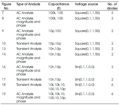
Table 1. Diodes
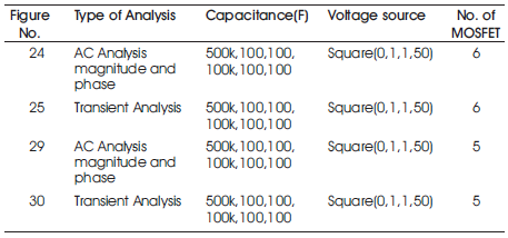
Table 2. MOSEFT
All the circuits (Figures 7 to 20) are analyzed in Circuit Sandbox, a free online tool from MIT, Cambridge, U.S .

Figure 7. AC Analysis (100k, 100)

Figure 8. AC Analysis Magnitude (100k, 100)

Figure 9. AC Analysis Magnitude and Phase (10p, 100)

Figure 10. Transient Analysis (10p, 10p)

Figure 11. Transient Analysis Magnitude

Figure 12. AC Analysis Magnitude

Figure 13. AC Analysis Magnitude and Phase

Figure 14. AC Analysis Magnitude and Phase (10n, 10p)

Figure 15. Transient Analysis

Figure 16. AC Analysis Magnitude and Phase (500k,100)
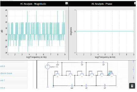
Figure 17. Transient Analysis
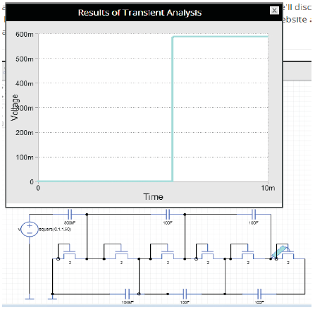
Figure 18. Transient Analysis
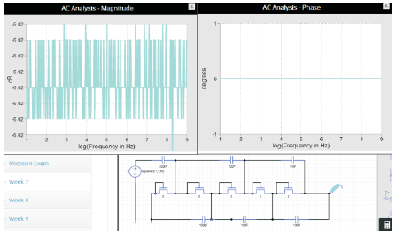
Figure 19. AC Analysis Magnitude
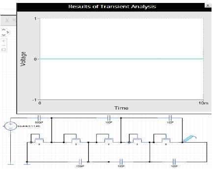
Figure 20.
The maximum terminal voltages of the Cockcroft Walton accelerators are typically between 200 and 1000 kV, thus the kinetic energies of the ions are rather low. Depending on the ions and the high voltage generator typical beam currents vary between 1μ A and 10 mA. Due to the progress in the field of ion sources not only light ions like hydrogen and helium but all kinds of heavy ions upto uranium can be accelerated. Using pulsed ion sources also pulsed beams with a high time-of flight resolution can be prepared.
The Cockcroft Walton accelerator is still used as pre-accelerator for large accelerator facilities. In medicine and industry it is used as a cheap neutron generator. Cockcroft Walton accelerators are also used in solid state physics, ion beam modification of materials, atomic physics, ion beam analysis of materials like Rutherford Back Scattering (RBS), Particle Induced X-ray Emission (PIXE), Particle Induced Gamma Emission (PIGE), Nuclear Reaction Analysis (NRA) and Elastic Recoil Detection (ERD), astrophysics and ecological research.