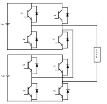
Figure 1. Schematic Diagram of the Inverter Topology Used to Verify the Proposed Hybrid Modulations
This paper deals with comparison of various Phase shifted Pulse width modulation techniques like Phase Shifted carrier, Hybrid Phase shifted carrier and newly proposed Hybrid Phase shifted carrier Pulse width modulation techniques.Comparison is done in terms of their design and their operation.
The multilevel converters achieve high-voltage switching by the use of series of voltage steps, each of the individual power devices are within the ratings. Among the multilevel inverters, the cascaded H-bridge topology is attractive in high-voltage applications, because it requires the least number of components to obtain the same number of voltage level.
High-voltage capability with voltage limited devices, low harmonic distortion and increased efficiency are some of the special features of multilevel inverter. The cascaded multilevel inverter appears to be superior to other at highpower rating because of its modular nature of modulation, control and protection requirements of each full bridge inverter [2-6]. Many new modulations have been developed to meet the growing number of MLI topologies. They are aimed to generate a stepped switched waveform that approximates an arbitrary reference signal with adjustable amplitude, frequency and phase fundamental component.
Most of the modulation methods developed for multilevel inverters is based on multiple-carrier arrangements with PWM. The carriers can be arranged with vertical shifts or with horizontal displacements. In this paper, horizontal displacements is considered i.e., Phase shifted carrier. With the use of hybrid modulation the performance of the MLI is improved. It also has the advantage of equal power dissipation among the power devices in a cell.
Figure 1 shows the single phase 5 level H-Bridge inverter topology. The number of H-Bridges are decided by
(2N+1)= M
Where N – Number of H-Bridges
M – Number of levels
Figure 1. Schematic Diagram of the Inverter Topology Used to Verify the Proposed Hybrid Modulations
Figure 2 shows the phase shifted carrier pulse width modulation. A multilevel inverter with M voltage level requires (M-1) triangular carriers. In the phase shifted multicarrier modulation, all the triangular carriers have the same frequency and peal to peak amplitude. There is a phase shift between any two adjacent carrier waves is given by φ cr = 360o /(M-1)[7-10]. The gate signals are generated by comparing the reference wave with the carrier waves. For a five level inverter, adjacent carrier waves are phase displacement is 90o . The phase displacement of each carrier wave is 0o , 90o , 180o and 270o .
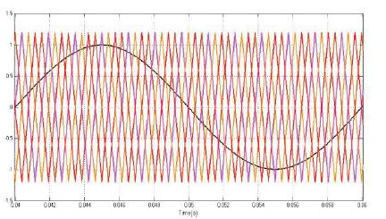
Figure 2. Phase Shifted Carrier PWM
Figure 3 shows the Hybrid phase shifted carrier PWM, which is in the shape of the diode bride full wave rectifier without any cut in voltage [1].
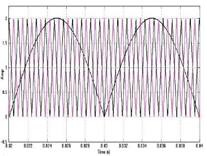
Figure 3. Hybrid Phase Shifted Carrier PWM
Figure 4 shows the modulation of PSC it has one reference wave which is compared with the four carrier waves and pulses were generated. This is the basic Phase shifted carrier PWM method. In addition to this another two types were developed. They are Hybrid phase shifted carrier and newly proposed hybrid phase shifted carrier. Table 1 shows the required number of references and carrier waves for each type of modulation HPSC is Hybrid phase shifted carrier and New HPSC is new Hybrid phase shifted carrier PWM modulation techniques.
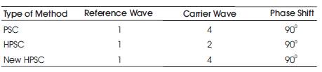
Table 1. Required Number of Carriers
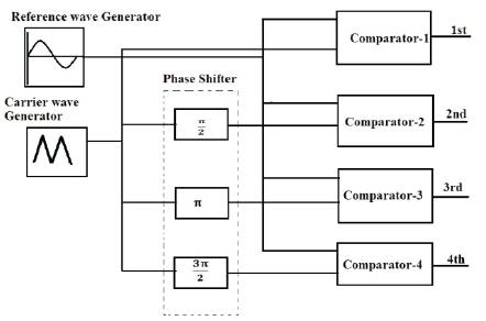
Figure 4. Block Diagram of Five Level Base Modulation PSC
A Sequential Switching Pulse (SSP) (A) is a square wave with 50% duty ratio and half the fundamental frequency. This signal makes every power switch to operate at MSPWM and FPWM sequence to equalize the power losses among the devices. FPWM is also a square wave signal synchronized with the modulation waveform. SSP and FPWM pulses are same for all inverter cells. The general structure of the SSHM (Sequential switching hybrid modulation) is shown in Figure 5[1].
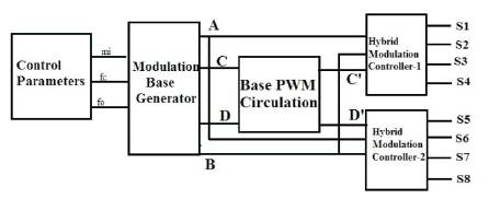
Figure 5. Sequential Switching Hybrid Modulation
In proposed hybrid modulation two base PWM circulators are involved. 1st and complement pulse of 3rd are fed to the 1st base PWM circulator, similarly the 2nd and complement pulse of 4th are fed to the 2nd base PWM circulator. The pulses which are obtained from the comparators shown in the Figure 4 are utilized. The pulses which are obtained from the Figure 6 [4-5] the base PWM circulator plays an important role.
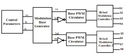
Figure 6. Sequential Switching of Proposed New Hybrid Modulation
A simple base PWM circulation scheme is to get resultant hybrid PWM circulation among the power modules. The scheme of five-level base PWM circulation consists of two 2:1multiplexer, and selects one among the two PWMs based on the time selection clock signal. The clock frequency is fo/4, makes the the time base for PWM circulation from one module to another in case of hybrid PSCPWM shown in Figure 5. Where as in case of proposed hybrid PSCPWM the clock frequency is increased to fo /2 which is shown in Figure 6.
Hybrid- Modulation ControllerHMC combines SSP, FPWM and MSPWM that produces SSHM pulses. It is designed by using a simple combinational logic for a five-level HPWM are expressed (1) as
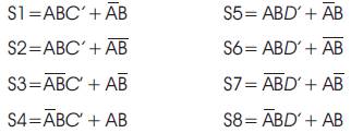
Where A is an SSP, B is an FPWM, C is an MSPWM for cell-I and D is an MSPWM for cell-II. Each gate pulse is composed of both FPWM and MSPWM. This process is not involved in the new hybrid PSCPWM. FPWM is completely eliminated.
The pulses which are obtained from various modulation methods are as follows.
Figure 7 is the pulses generated from the PSCPWM process by the comparison of the reference wave with the carrier waves pulses will be generated. S1 and S2 are similar pulses and S3 and S4 are similar. But the two pulses will be turned on at complementary timings.
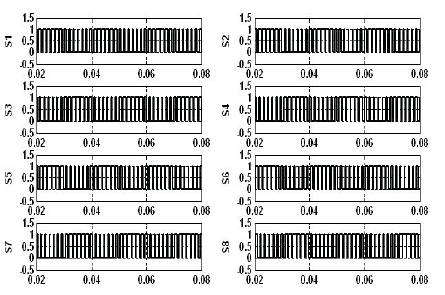
Figure 7. Five Level PSCPWM Pulses
Figure 8 is the pulses representing the low and high frequency PSCPWM pulses A is the fo , B is fo /2, C and D are the pulses from the comparators 1 & 2. The C' & D' are the combination of C and D, such that for the first cycle the respective pulse will be the output for the second cycle another pulse will the output pulse. This is obtained by using the Base PWM circulation method. Figure 9 are the five-level hybrid PSCPWM pulses generated by the hybrid modulation controllers.

Figure 8. Low and High Frequency PSCPWM Pulses at m1 =1 and fc =1050
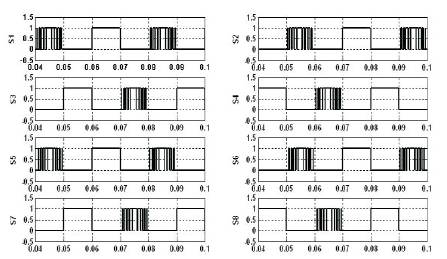
Figure 9. Five Level Sequential Switching HPSPWM Pulses
Figure 10 is the five-level new hybrid PSCPWM pulses generated from the circuit shown in Figure 6. All the three method pulses obtained are fed to the MLI with the corresponding pulse names given to the respective switches of MLI.
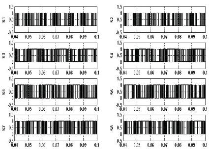
Figure 10. Five Level New HPSCPWM Pulses
Figure 11 shows the Simulink model of the single phase 5 level cascaded H-Bridge with R-load.
The simulation is done by using MATLAB/SIMULINK software. The output voltage waveforms are observed for the three PWM methods
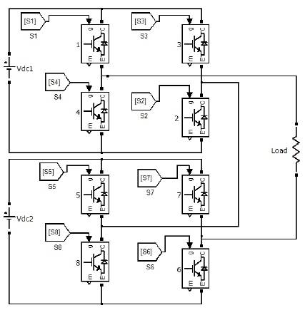
Figure 11. Simulation Circuit of MLI
For justification of comparison, a performance index namely Total Harmonic Distortion (THD) was chosen to evaluate the three techniques and plotted. The THD is calculated using the equation (2). Up to 50th order of harmonics is taken in to consideration [8].
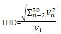
Figure 12(a) shows the output voltage waveform of the five level inverter voltage, which is controlled by the Phase shifted PWM technique. Figure 12(b) shows the spectrum analysis of the voltage waveform, it is having the THD of 36.05%
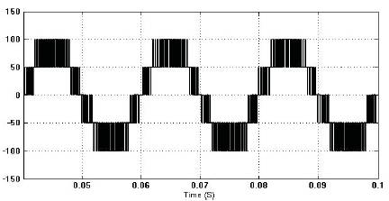
Figure 12 (a). Line to Neutral Output Voltage Waveform for a Five Level Inverter at mi =1 and fc =1050hz of PSCPWM
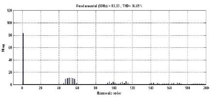
Figure12 (b). Harmonic Spectrum of the Line to Neutral Output Voltage of PSCPWM
Figure 13(a).shows the phase voltage waveform of the five level inverter with the Hybrid Phase shifted PWM method and Figure13(b) shows the Spectrum analysis of the corresponding voltage waveform with the THD value of 26.16%.

Figure 13(a). Line to Neutral Output Voltage Waveform for a Five Level Inverter at mi=1 and fc =1050 Hz of HPSCPWM
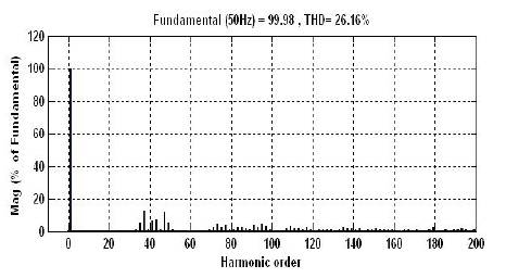
Figure 13(b). Harmonic Spectrum of the Line to Neutral Output Voltage of HPSCPWM
Figure14 (a) shows the phase voltage waveform of the five level inverter with the new Hybrid Phase shifted PWM method and Figure 14(b) shows the Spectrum analysis of the corresponding voltage waveform with the THD value of 26.9%
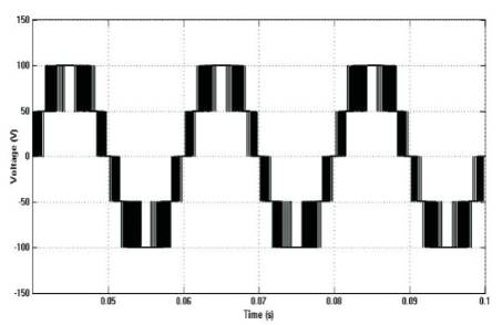
Figure 14 (a). Line to Neutral Output Voltage Waveform for a Five Level Inverter at m1 =1 and fc =1050Hz of New HPSCPWM
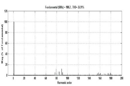
Figure 14(b). Harmonic Spectrum of the line to Neutral Output Voltage of new HPSCPWM.
Figure 15 shows the THD% Vs modulation index curve. The modulation index is varied from 0.5-1. It is observed that new hybrid PSCPWM is having the less THD when compared to other PWM techniques.
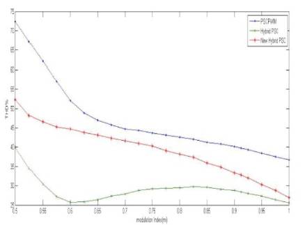
Figure 15. THD% Vs Modulation Index for Five-Level Inverter at fc =1050.
An optimized hybrid phase shifted PWM control scheme for cascaded multilevel inverter is proposed in this paper. A new hybrid PSCPWM controller is designed to generate gate pulses for the inverter switches. When compared with the conventional PWM and the Hybrid PWM techniques with the new hybrid PWM it acts as a moderate in between the two types of methods. Though the obtained values a lesser than the Hybrid PSCPWM the number of control circuit components were reduced when compared to it.