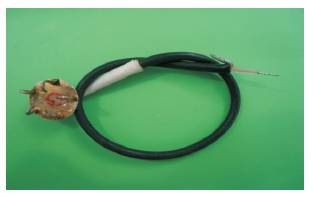
Figure 1. EEG Electrode
Electroencephalograph (EEG) is a technique commonly used in medical and research fields to record the electrical activities of the brain. The EEG signals are recorded from the surface of the scalp metallic electrodes. The EEG signals are within the range of (0.5-50μV), the raw signals are originated from different areas of the brain. The locations of these electrodes on the scalp are specified according to the 10-20 international system.
Measuring the EEG signals is usually difficult due to small signal magnitude of the EEG signals and large DC offset voltage incorporated with the measuring process. The DC-offset in EEG signal is a result of many factors, like electrode-skin interface, amplifier input bias current mismatch, input impedance, offset voltage, and voltage drift with temperature and aging. The signal is amplified in two stages and digitized using a 24-bit analog to digital convertor (ADC). The DCoffset was treated using auto-zeroing technique, along with the use of high precision electronic components. The theoretical design was first simulated using TINA-TI software, then the PCB's were designed using Eagle software, and implemented experimentally. EEG signals were acquired and recorded for different people and it seems satisfactory for the diagnosis by doctors.
EEG is spontaneous cortical electrical activity recorded at the scalp. The human EEG was discovered by Berger in the 1800s using a primitive galvanometer with a surface electrode electrical oscillation [1]. Every stimulation of nerve cells in the brain elicits rhythmic potential oscillations of a few microvolts. These oscillations can be conducted from the body surface (scalp) by metal electrodes and recorded as an electroencephalogram. The main waves (Alpha (α), Beta(β), gamma (δ), delta (δ), and Theta (θ) waves) vary from region to region, especially in their height (amplitude) and frequency. Hence it is possible to make relatively crude interpretations concerning normal and pathological activities of the brain [2].
EEG waveforms generally are classified according to their frequency, amplitude, and shape, as well as the sites on the scalp at which they are recorded. The most familiar classification uses EEG waveform frequency [4]. The frequencies are as follows: α: 8–13Hz, β: 14–26Hz, δ: above 30Hz, δ: 0.5–4Hz, and θ: 4–7.5Hz [3].
The EEG waves are measured on the scalp using different types of metallic electrodes. The Silver/Silver Chloride (Ag/AgCl) electrode is the most commonly used electrode. The electrodes used here are home-made from high quality silver and the tips of the circumferential rods are treated with sodium hypochlorite solution. A chemical interaction will take place between the silver and the hypochlorite solution resulting in coating the tips of the rods with silver chloride (AgCl). The tips are curved inside to provide more surface contact with the scalp. The Ag/AgCl electrode is shown in Figure 1.
Figure 1. EEG Electrode
Since the human head consists of different layers including the scalp, skull, brain, and many other thin layers in between, the skull attenuates the signals approximately one hundred times more than the soft tissue. In order to record these weak signals, the signals should be amplified with a total gain of about 100.000. This gain will also amplify the total DC-offset of the amplification stages. The DC-offset in EEG signal is a result of many factors, like electrode-skin interface, amplifier input bias current mismatch, input impedance, offset voltage, and voltage drift with temperature and aging [4]. The consequences of DC-offset on the circuit performance include gates saturation, ADC Errors, measurements inaccuracy, etc. Thus a solution to remove this offset is important at this level of precision measurements. One of the different solutions of the DC offset is the auto-zeroing technique using a feedback integrator.
Bio-potentials exhibit small amplitudes and low frequencies. Moreover, bio-potential measurements are corrupted by environmental and biological sources of interference. Therefore, the essential, although not exhaustive, design considerations include proper amplification and bandwidth, high input impedance, low noise, and stability against temperature and voltage fluctuations [5].
The system was designed so as the amplification is performed mainly in two stages; the first stage is a differential amplifier with ultra-low offset, drift, and bias current specifications and designed with relatively low gain. The second stage with higher gain and auto-zeroing technique is performed here to cancel the total offset voltage that was generated and amplified by the two stages. RC low pass filter with cutoff frequency at 35Hz is used too to remove the effect of the electrical power lines noise on the signal and finally the signal is digitized using 24-bit ADC.
Differential AmplifierThe differential amplifier used as a bio-potential amplifier is characterized with low input bias current, low offset voltage, and high common mode rejection ration (CMRR). The offset drift over temperature is also another parameter which should be considered to reduce the amplifier saturation especially when high gain and long time operation are used.
Practically, operational amplifiers draw input bias current (IB) from each of their input terminals due to bias requirements. These currents flow through the resistances connected to the inputs (R1 and R3) and produce small voltage drops across those resistances. In high-precision DC amplifier, these voltage drops are demanded to be equal for both inputs, and therefore cancelled. If these voltage drops are equal and the CMRR of the operational amplifier is good, there will be considerable cancellation and improvement in DC accuracy. For the amplifier chosen here, AD8571, the bias current is typically 1nA, and the input resistors are equal and low 1KΩ.
A large CMRR is a prerequisite for efficient suppression of unwanted signal components that are common to the inputs. Modern Electrophysiological (EP) amplifiers achieve a CMRR of 80dB or even better [9]. The CMRR of the operational amplifier AD8571 is 145dB typical across the temperature range of the device −40°C to +125°C. With the high input impedance of the Op-Amp AD8571, Additional factors in amplifier design include high input impedance. This determines the amount of current that an impressed voltage will drive. High input impedance leads to a low current being drawn and, consequently, even a high resistance scalp-electrode interface will be quite immune to picking up the environmental electrical noise which surrounds us [1].
The amplifier offset Voltage (Vos ) is generated due to a number of unbalances in the op amp's internal transistors and resistors. This voltage, along with offset voltage drift due to temperature and aging, is an important part added to the total offset of the amplifier, representing another factor to be considered when selecting an amplifier for precise measurements. With an offset voltage of only 1μV and drift of 0.005μV/°C, the AD8571 is perfectly suited for applications where error sources cannot be tolerated over their operating temperature range. The gain of the first stage, the differential amplifier, is set to 100.
Auto-Zeroing CircuitThe second stage of amplification performs the autozeroing technique using two OPA277 Op-Amp's, and one low on-resistance (RON ), low voltage, dual single- pole/double-throw (SPDT) analog switch, MAX4685. The first Op-Amp (U1) amplifies the output of the differential amplifier with gain of 500, and the second Op-Amp (U2) is an integrator. As shown in Figures 2 & 3.
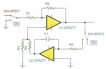
Figure 2. Auto-Zeroing (Measuring Phase)
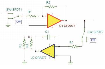
Figure 3. Auto-Zeroing (Zeroing Phase)
The total offset voltage contribution (VosT ) for the first and second stages is calculated as follows
VosT= [(offset of the first stage) × 100 + (total offset of the second stage)]× 500
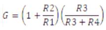
The parallel combination of the resistors R3 and R4 should be equal to the parallel combination of the resistors R1 and R2 to compensate the effect of offset voltage generated from bias currents on these resistors.
This is to make the total loop gain less than 1 and thus the effect of the integrator on the circuit performance will take more time. The total loop gain is
The auto-zeroing process has two time phases, Measuring Time (Tm) and Zeroing Time (Tz ).
In measuring time, the first switch SW-SPDT1 and the second switch SW-SPDT2 are on the ON state, as shown in Figure 1. and the signal from the EEG signal is measured. So this is the signal measuring phase. With this phase, the offset is rising as the amplifiers are working, and at the same time, the integrator U2 is disconnected from the signal path.
Here , the first switch SW-SPDT1 and the second switch SWSPDT2 are on the OFF state, as shown in Figure 2. The VosT will be delivered by the integrator to the non-inverted terminal of U1, thus VosT will be cancelled and U1 will return to the initial total offset of the first stage, and this is the autozeroing phase. At this point, we can realize the importance of choosing an ultra-low offset specification amplifier to be as a differential amplifier for the first stage. In this research, the Measuring Time (Tm) is selected to be 18 seconds and the zeroing time is of 2 seconds. In the hospital, The time required to record a complete diagnostic EEG session is about 30 minutes. Thus the zeroing time is very low compared to the total time required for a complete diagnostic EEG, and will result in no missing data.
The auto-zero principle can be used not only to cancel the amplifier offset but also to reduce its low-frequency noise, for example 1/ƒ noise. But unlike the offset voltage, which can be considered constant, the amplifier's noise and particularly its wide band thermal noise component is time-varying and random. The efficiency of the autozeroing process for the low-frequency noise reduction will thus strongly depend on the correlation between the noise sample and the instantaneous noise value from which this sample is subtracted. The autocorrelation between two samples of 1/ƒ noise separated by a time interval t decreases much slower with increasing t than it does for white noise, assuming they have the same bandwidth. The AZ process is thus efficient for reducinmg the 1/ƒ noise but not the broadband white noise [6].
In this research, we selected the Sigma-Delta converter as it offers high resolution, high integration, making it a good ADC choice for medical applications [7]. The resolution of the converter is determined by the smallest amplitude that can be sampled. This is obtained by dividing the voltage range of the A/D converter by 2 raised to the power of the number of bits of the A/D converter. A/D converter usually uses minimally 12 bits (discerning 4,096 value levels). Ability to resolve 0.5 μV is recommended. Sufficient sampling rate is required, at least double of the highest frequency component of our interest [8].
Here we used a low-power, 8-channel, 24-Bit analog Front-End, ADS1298, which is particularly used for Biopotential Measurements. The ADS1294 is a multichannel, simultaneous sampling, 24-bit, delta-sigma (ΔΣ) ADC with built-in programmable gain amplifiers (PGAs), internal reference, and an onboard oscillator. With 3V supply voltage, the resolution of this ADC will be about 0.18μV. The ADC offers a data rate from 250SPS to 32kSPS. The internal oscillator generates a 2.048MHz clock.
The design was firstly simulated using TINA, a circuit simulation program from Texas instruments, and the results were accepted. The PCB's are designed using Eagle 5, from CadSoft Computer GmbH, Figure 3.
The International Federation of Societies for Electroencephalography and clinical Neurophysiology has recommended the 10-20 system of electrode placement, which consists of 19 active electrodes plus two references (linked to earlobes or mastoids). The distance between each electrode is either 10% or 20% of the total edge distances (e.g. nasion-inion), hence the name 10-20 [9].
In this work, we used five printed circuit boards (pcb) to cover 10 electrodes placed on specific locations on the scalp according to the 10-20 international. Each pcb, in Figure 3a, contains one differential amplifier AD8571, two OPA277, and one MAX4685. With this design, the small four pcb's are placed on the cap close to the electrodes, and this, with the use of coaxial cables, will reduce the environment noise effects on the EEG signal quality. The outputs of these pcb's is collected by boards on each side of the EEG cap, filtered and then fed to the ADC to be digitized and displayed on the computer.
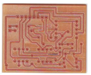
Figure 3a. Implemented PCB
The whole system was fabricated and tested on several patients. The results were good and accepted. The EEG signal of a 35 year old male patient is shown in Figure 4. and one more magnified signal is shown in Figure 5. The alpha rhythm of a 32 male patient is shown in Figure 6. The DC-offset of these signals is treated successfully.
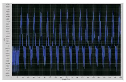
Figure 4. The EEG Signals of a 35 years Old Male Patient
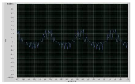
Figure 5. Magnified EEG Signal
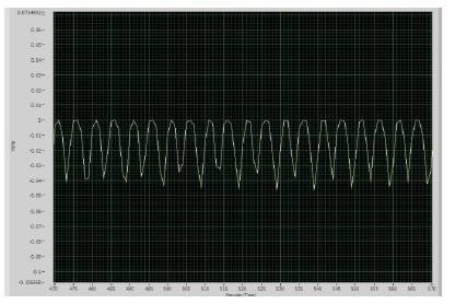
Figure 6. EEG Alpha Rhythm
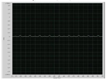
Figure 7. The Recorded Signal During Zeroing Phase
The signal recorded during the zeroing phase is shown in Figure 7. The noise of the devices are fairly low and has minimum effect on the recorded signal.
The selection of the ultra low offset specifications of the Operational amplifiers along with Auto-zeroing technology makes the design effective and stable over long work duration. The Auto-zeroing technology makes the design effective and stable over long work duration. The time for each EEG montage protocol require about 30 minutes, thus the total time required for a complete EEG session is about 2 hours. Therefore a stable system is required to obtain high accuracy measurements.
Also, the use of the curved-ended Ag/AgCl electrodes with high CMMR, ultra-low offset amplifiers enabled to record the EEG signal directly from the patient without the need for patient preparations like; shaving the head, skin abrasion, and use EEG gel on the site of electrodes. These preparations are usually refused by female patients and not recommended for patients with infectious diseases. The unfavorable part of the system was the weight of the cap, as it is heavier than the ordinary cap used by electroencephalographers.