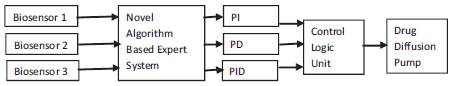
Figure 1. Automated Drug Delivery Unit Top Level Block Diagram
Disease classification and drug diffusion are the two major tasks that have to be performed by automated drug delivery unit. Both these operations have to be performed with utmost care and the performance of the system should be reliable and reproducible. The electrical signals that are produced by the sensor array network, that indicate the concentration of analyte solution based on the kind of disease being detected, is used as the input to the classification problem. The developed model is used for classification cancer data obtained from the sensor array network. In this paper design of controller for drug diffusion is also presented. Both the novel algorithm based expert system and the controller logic for drug diffusion to measure and analyze the real time performance of the system. A detailed discussion on the design, modelling and implementation of the expert system and drug delivery unit is presented.
Cancer diagnosis and treatment are of great interest due to the widespread occurrence of the diseases, high death rate, and recurrence after treatment. According to the National Vital Statistics Reports, from 2002 to 2006 the rate of incidence (per 100,000 persons) of cancer in White people was 470.6, in Black people 493.6, in Asians 311.1, and Hispanics 350.6, indicating that cancer is widespread among all races. Lung cancer, breast cancer and prostate cancer were the three leading causes of death in the US, claiming over 227,900 lives in 2007 alone, according to the National Cancer Institute. Cancer is also greatly feared due to recurrences, as although treatable, tumors can return after a period of time, even after chemotherapy, surgery, or radiotherapy. Survival of a cancer patient depends heavily on early detection and thus developing technologies applicable for sensitive and specific methods to detect cancer is an inevitable task for cancer researchers. Existing cancer screening methods include: (i) The Papanicolau test for women to detect cervical cancer and mammography to detect breast cancer, (ii) Prostate-Specific Antigen (PSA) level detection in blood sample for men to detect prostate cancer, (iii) Occult blood detection for colon cancer, and (iv) Endoscopy, CT scans, X-ray, ultrasound imaging and MRI for various cancer detection and (v) CA125 antigens essential for the early detection of ovarian cancer. These traditional diagnostic methods however are not very powerful methods when it comes to cancer detection at very early stages. As well, some of the screening methods are quite costly and not available for many people.
Figure 1 shows the top level block diagram of the proposed automated drug delivery unit that is used to detect cancer cells present in the blood or the cells and can diffuse drug from storage in controlled manner. The drug diffusion process is controlled by a control logic that is driven by three controllers (PI, PD and PID). Biosensors are placed in an array, arranged in a manner to capture maximum number of target molecules is interfaced with the expert system. The expert system receives the electrical equivalents of concentration of cancer cells captured by the receptors placed on the gate of nanowire sensors. Based on the voltage or current equivalents received, the expert system which is designed based on novel algorithm processes the sensor signals and performs classification. The classified output generated from the expert system is used to drive the drug diffusion control unit. Many researchers have attempted in building a physical model to illustrate the functionality of biosensors and drug diffusion process.
Figure 1. Automated Drug Delivery Unit Top Level Block Diagram
The major focus of this paper is to discuss the design and VLSI implementation of novel algorithm architecture and control unit that can be realized on a chip and can be integrated with a sensor array chip. The software reference model is tested based on an experimental setup developed in Matlab environment [1]. The major challenges are integration of the designed building blocks as a complete system and testing the system functionality. The individual blocks are designed and tested for its functionality based on mathematical models developed. Sensor array models are not realized on hardware, functionality of the modelled array networks have been verified [2]. In order to integrate the sensor array with the expert system for disease classification, standard set of data consisting of cancer information is considered and is used in analyzing the performances of expert system. In this work it is assumed that the designed array sensor model when implemented using VLSI technology or nanotechnology can generate the same set of parameters available in the data base for cancer cell detection.
The expert system processes the data and detects the presence of cancer, and classifies diseases. Based on the classification process, the expert system also generates control signals to the control unit to diffuse corresponding drug stored, and the feedback system in the control unit constantly monitors the diffusion process. The control unit required to control the drug diffusion pump is modelled and implemented. The expert system and control unit have been integrated and implemented on FPGA to understand the hardware implementation performances of the system. Integrating the diffusion pump with the control logic is not within the scope of this project.
Based on the disease detected and classified, the expert system drives the drug diffusion unit for drug delivery. Output of detection unit is interfaced with drug delivery unit. It is assumed that the actuator that controls the drug storage unit to deliver the drug is available, only the control unit that is required to trigger the actuator is to be designed. The control unit plays a vital role, as the cancer cells gets detected, the control units need to respond immediately to trigger the actuator. Transient and steady state response for the control unit are very critical parameters. A PID controller is designed to drive the motors that diffuse the drug. The control logic developed is used in drug selection. The actuators are triggered based on the control logic that not only selects the drug but also drives the motors to diffuse appropriate drug. The design of drug diffusion unit is presented in next section.
This block implements a 32-bit digital PID controller with automatic correction. The inputs are a reference input (ref) and a feedback input (fdb) and the output (out) is the saturated PID output. Figure 2 shows a PID controller. Three controllers such as proportional, proportional-integral and proportional-differential are used to control the actuator; a feedback loop used to monitor the drug diffusion, based on the feedback signal the control unit monitors the drug diffusion process.
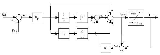
Figure 2. Simulink Model of PID Controller
The differential equation describing the PID controller before saturation that is implemented in this block is and is given by equation (1)
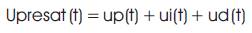
Where, upresat is the PID output before saturation,
Up is the proportional term,
Ui is the integral term with saturation correction, and
Ud is the derivative term.
The proportional term is up (t) = Kpe(t), where Kp is the proportional gain of the PID controller and e(t) is the error between the reference and feedback inputs.
The integral term with saturation correction is
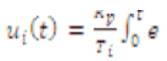
Where Kc is the integral correction gain of the PID controller. The derivative term is
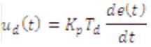
Where Td is the derivative time of the PID controller. In discrete terms, the derivative gain is defined as Kd = Td/T, and the integral gain is defined as Ki = T/Ti, where T is the sampling period and Ti is the integral time of the PID controller.
Simulink model for the proposed architecture is developed and is simulated. The Simulink model is as shown in Figure 3. The model consists of a drug decision unit that selects the corresponding drug as well as decides the amount of drug to be diffused. The selected quantity is taken as reference and based on this information the controller drives the drug diffusion unit and the results are monitored on scope. The results obtained are presented.
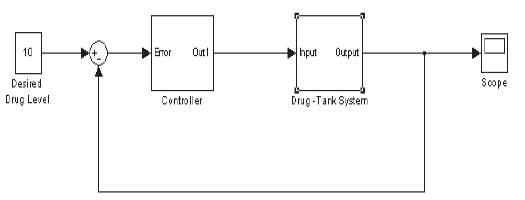
Figure 3. Simulink Model of Drug Diffusion Unit
The drug diffusion model consists of:
The controller block contains a simple proportionalintegral- derivative controller. Once the classification algorithm detects the cancer cells based on the processing carried out in the expert system, a suitable drug is selected based on the patients history and other parameters such as height, weight, age and previous history. A suitable number corresponding to the parameters is used to set the desired drug level. The controller unit triggered by the expert system, the PID controller diffuses the drug. The transient response of the simulink model is captured and is shown in Figure 4.
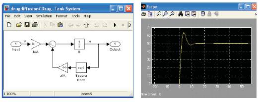
Figure 4. Simulation Results of Drug Diffusion Model
The control unit has a transient response and overshoots the normal value by 10% and settles to the nominal value in less than 10ms, this is achieved by the use of PID controller. Overshoot and settling time of the proposed unit is better in performance. Use of only proportional or PI or PD controller may not be able to get the required results. Thus the developed system is suitable for drug diffusion Unit.
For real time implementation of expert system and PID controller logic, it is requried to verify the hardware performances of the complex system. The complexity of expert system is large as it consists of 5 neuron and each neuron receives 100 input samples, thus the total number of multipliers that are required together in the hidden and output layer is 21605, number of adders required is 2 and sigmoid transfer function. Similarly the PID controller requires 4 multipliers, 4 adder/subtractor unit, two accumulators and one transfer function. The fundamental building blocks of expert system and PID controller are adders, multipliers, memory elements and control logic. Various multipliers and adders are realized and the results are verified on FPGA for area, power and speed performances.
Multiplier logic presented in previous section is modeled using Verilog HDL and verified using ModelSim. In order to estimate the performances of various multipliers, FPGA implementation is carried out of various multipliers are presented in this section.
BCSD (Binary Canonic Sign Digit) multiplier is a sequential multiplier involving shifting register for each clock cycle and accumulating partial products. It is totally characterized by the characteristics of clock and a load signal is taken to load registers with inputs synchronized with clock. Since the multiplier designed is of 12 bits wide it takes 12 clock cycles to reproduce the output. This multiplier is synchronized with clk i.e. is any changes in input signal will be recognized only at the rising edge of clk. Whenever, the load signal goes to high when the operation is in progress, the previous data will be overwritten, and the output is obtained for new inputs only. Hence, load should be asserted only after 12 cycles, after the completion of one operation by the multiplier [3-7].
Array multiplier is a combinational circuit; no storage elements synchronized with clk. Delay in the output is caused by the change in the input that depends on the propagation delay of circuit elements used in the hardware implementations by the designer. Carry propagation is the critical factor and use carry save adder chain for improving the speed [7-12].
Modified booth is a sequential multiplier which is synchronized with clock for each and every operation. In general, Booth multiplier will take 'n' clock cycles depending on the word length of operand and Modified booth of radix-4 takes n/2 clock cycles to complete one operation. Further, it can be reduced by increasing radix with a penalty in complexity of hardware [12-14].
Wallace tree multiplier is the fastest multiplier with irregular structure, pure combinational circuit with carry save adder chain and more complex hardware loop structure. First add all the available product terms and then the partial products in a tree structure without affected by delays in carry propagation [14-16].
Baugh Wooley multiplier is a modified version of array multiplier, is combinational multiplier to handle the signed numbers multiplication. The speed of sequential multipliers can be increased by encoding them with high radix, with a penalty of increase in complexity. All simulated programs cannot be synthesized and restricts the designer in making effective hardware description [16-19]. Further simulation tools verify the functionality of logic only. They can't guarantee that the design, works when placed into FPGA. In this work, all the designs are verified and proved to be functional. Area and timing performances based on FPGA implementation is compared for all the multipliers.
From the synthesis report obtained BCSD multiplier utilizes memory of 180 MB and the maximum clock frequency is up to 84.946 MHz (11.772 ns) is to estimate approximately and in most cases it gives maximum time that would be more than the actual timing of the design. From the results obtained from map report, 8.147 ns is the minimum period without considering wiring delays of the circuit. Actual timing after routing will be in between the two values of time, also there would be no combinational delay for a sequential circuit. Observing carefully after giving pin assignment the floor plan will be shifted near to the I/O blocks reducing the delays. Table 1 shows the synthesis reports of multipliers in terms of number of slices, number of 4 input LUTs, usage memory, combinational delay, the minimum pin delay.
Table. 1 shows the performance measures of multipliers constraints, delay and number of gates of multipliers. From the reports obtained it is concluded that, better optimization is obtained for memory of 29 MB and 2 ns of timing. With the help of high radix algorithm, the clock frequency is increased and number of additions/ subtractions is more in comparison with BCSD.
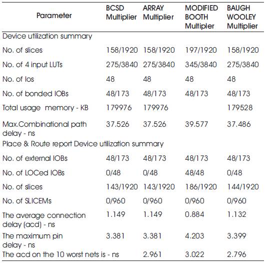
Table 1. Synthesis Report of Multipliers
The design utilizes multipliers, adder/subtractor, comparators and registers. From the synthesis results it is found that the design operates at maximum frequency of 292 MHz, and occupies 148 slices. Thus the design is optimized for area and speed. Table. 2 presents the results of PID controller logic synthesized on Virtex 2 pro FPGA consisting of 30 million gate capacity. The PID controller design requires sub blocks such as multipliers, adder/subtractors and registers. PID control logic operates at maximum frequency of 1045 MHz, thus is suitable for automated drug delivery unit.
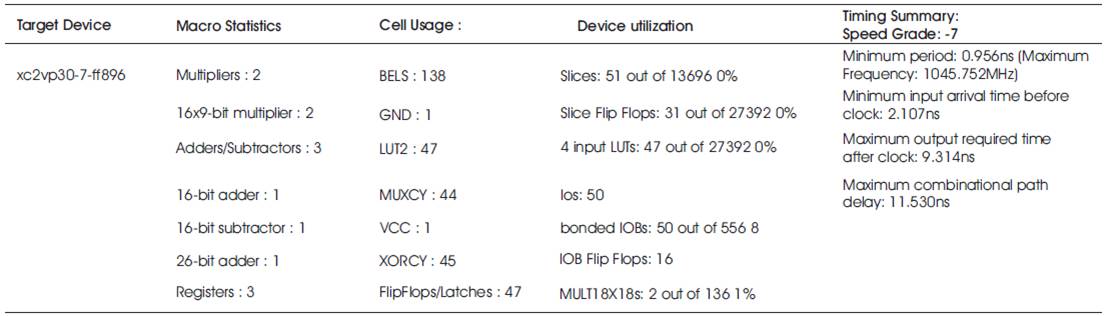
Table 2. PID Control Logic Statistics
The output data generated from the expert system is used to control the PID controller to activate the drug diffusion pump. Software reference model for expert system as well as PID controller is developed and modeled using Matlab and simulink model. Further the novel algorithm model and the PID controller model is modeled using HDL and is synthesized targeting FPGA. Synthesis results show the developed system is ideal for real time implementation of automated drug delivery unit
The authors would like to acknowledge Nanohub.org for providing permission to access the biosensor labs simulation tools and to carry out the experiments. The authors also acknowledge the support and guidance provided by Cyril Prasanna Raj P., MSR School of Advanced Studies, Bangalore. His suggestions and valuable guidance has helped us in carrying out the experimental analysis.