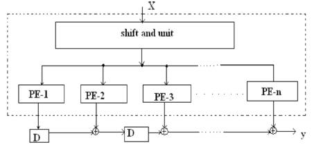
Figure 1. Transposed Direct form of an FIR filter
Reconfigurability and low complexity are the two key requirements of finite impulse response (FIR) filters. Two new efficient reconfigurable architectures namely constant shift method (CSM) and programmable shift method (PSM) of low complexity are used for design of higher order finite impulse response (FIR) filters. The FIR filter architecture is capable of operating for different wordlength filter coefficients without any overhead in hardware circuitry. The CSM results in higher speed whereas the PSM results in lower area. These methods are based on the binary common subexpression elimination (BCSE) algorithm using canonical signed digit (CSD) representation of coefficients. The CSD representation is widely used in implementing multiple constant multiplication because it guarantees the least number of additions for a given constant multiplication. Hence the CSM architecture is used for high speed applications and the PSM architecture is used in applications where area and power have to be minimized. The experimental results are synthesized and major parameters like area, delay, power are compared for both CSM and PSM architecture using Xilinx ISE 8.1tool.
FIR digital filters find extensive applications in mobile communication systems for applications such as channelization, channel equalization, matched filtering, and pulse shaping, due to their absolute stability and linear phase properties. The filters employed in mobile systems must be realized to consume less power and operate at high speed. The complexity of FIR filters is dominated by the complexity of coefficient multipliers. It is well known that the common sub expression elimination (CSE) methods based on canonical signed digit (CSD) coefficients produce low complexity FIR filter coefficient multipliers [2]. In [5] they have the binary common subexpression elimination (BCSE) method which provided improved adder reductions and thus low complexity FIR filters compared to [2]–[ 4]. In [7] the concept of reconfigurable multiplier block (ReMB) was introduced. The ReMB will generate all the coefficient products and a multiplexer will select the required ones depending on the input. It was shown that by pushing the multiplexer deep into the multiplier block design, the redundancy can be reduced. The resulting specialized multiplier design can be more efficient in terms of area and computational complexity compared to the general-purpose multiplier plus the coefficient store [7]. But the ReMB proposed in [7] has its area, power, and speed dependent on the filterlength making them inappropriate for higher order FIR filters. In this paper, two architectures are designed that integrate reconfigurability and low complexity to realize FIR filters. The FIR filter architectures are called constant shifts method (CSM) and programmable shifts method (PSM). The preliminary design of two architectures is taken from a recent conference paper [6]. In this paper, elaboration of the CSM and PSM architectures was introduced in [6] by providing the detailed design. Also two CSD based methods based on our CSM and PSM are designed. The architectures consider coefficients as constants (as they are stored in LUTs) and input signal as variable. The coefficient multiplication in such a case is known as multiple constant multiplications (MCM), i.e., multiplication of one variable (input signal) with multiple constants (filter coefficients). The MCM is then optimized for eliminating redundancy using our BCSE algorithm [5] to minimize the filter complexity. The CSM focuses on the implementing FIR filters by partitioning the filter coefficients into fixed groups.
The PSM has a pre-analysis part which eliminates the redundancy in filter coefficients using the BCSE algorithm. The advantage of CSM is that it produces high-speed filters at the cost of a slight increase in area and power consumption. On the contrary, the PSM produces filters with low area and power consumption at the cost of a slight increase in delay. Another advantage of PSM is that the wordlength of the filter coefficients can be dynamically changed without any modification in the hardware.
This section reviews the BCSE algorithm [5], which deals with the elimination of redundant binary common subexpressions (BCSs) that occur within the coefficients. The BCSE technique focuses on eliminating redundant computations in coefficient multipliers by reusing the most common binary bit patterns (BCSs) present in coefficients. An n-bit binary number can form 2n − (n + 1) BCSs among themselves. For example, a 3-bit binary representation can form four BCSs, which are [0 1 1], [1 0 1], [1 1 0], and [1 1 1]. These BCSs can be expressed as [0 1 1] = x2 = 2-1x + 2-2x, [1 0 1] = x3 = x + 2-2x, [1 1 0]= x4 = x + 2-1x, and [1 1 1]= x5 = x + 2-1x + 2-2x, where x is the input 5 signal. Note that other BCSs such as [0 0 1], [0 1 0], and [1 0 0] do not require any adder for implementation as they have only one nonzero bit. A straightforward realization of above BCSs would require five adders. However x2 can be obtained from x4 by a right shift operation (without using any extra adders): x2 = 2-1x + 2-2x = 2-1(x + 2-1x) = 2-1x4. Also, x5 can be obtained from x4 using an adder: x5 = x + 2-1x + 2-2x = x4 +2-2x. Thus, only three adders are needed to realize the BCSs x2 to x5 . The number of adders required for all the possible n-bit binary subexpressions is 2n-1 -1 [5]. The number of adders needed to implement the coefficient multipliers using the binary representationbased BCSE is considerably less than the CSD-based CSE methods [5]. The FIR filter architecture is based on transposed direct form as shown in Figure 1. In the transposed direct form, the coefficient multipliers (shown as dotted outline in Figure 1) share the same input and hence commonly known as multiplier block (MB).
Figure 1. Transposed Direct form of an FIR filter
The MB reduces the complexity of the FIR filter implementations, by exploiting the redundancy in MCM. Thus, redundant computations (partial product additions in the multiplier) are eliminated using BCSE. The BCSE method in [5] was formulated as a low complexity solution to realize application specific filters where the coefficients are fixed. In the next section, two architectures that incorporate reconfigurability into the BCSE-based low complexity filter architecture. Although BCSE is used to illustrate reconfigurable filter architectures in this paper, it must be noted that the architectures can be used for any CSE method with appropriate modifications.
In this section, the architecture of the FIR filter is presented. Our architecture is based on the transposed direct form FIR filter structure as shown in Figure 1. The dotted portion in Figure 1 represents the MB. In Figure 1, PE-i represents the processing element corresponding to the ith coefficient. PE performs the coefficient multiplication operation with the help of a shift and add unit which will be explained in the latter part of this section. The architecture of PE is different for CSM and PSM. In the CSM, the filter coefficients are partitioned into fixed groups and hence the PE architecture involves constant shifters. But in the PSM, the PE consists of programmable shifters (PS). The FIR filter architecture can be realized in a serial way in which the same PE is used for generation of all partial products by convolving the coefficients with the input signal (h * x[n]) or in a parallel way, where parallel PE architectures are employed. The first option is used when power consumption and area are of prime concern. The basic architecture of the PE (dotted portion) is shown in Figure 2.
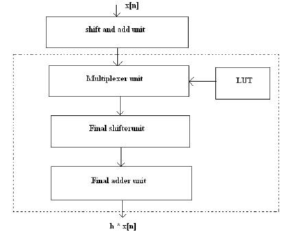
Figure 2. Architecture of the Existing Method.
The functions of different blocks of the PE are explained below.
It is well known that one of the efficient ways to reduce the complexity of multiplication operation is to realize it using shift and add operations.
In contrast to conventional shift and add units used in previously reconfigurable filter architectures, the BCSsbased shift and add unit in our CSM and PSM architectures are used. The architecture of shift and add unit is shown in Figure 3. The shift and add unit is used to realize all the 3-bit BCSs of the input signal ranging from [0 0 0] to [1 1 1]. In Figure 3, “x>>k” represents the input x shifted right by k units. All the 3-bit BCSs [0 1 1], [1 0 1], [1 1 0], and [1 1 1] of a 3-bit number are generated using only three adders, whereas a conventional shift and add unit would require five adders. Since the shifts to obtain the BCSs are known beforehand, PS is not required. All these eight BCSs (including [000]) are then fed to the multiplexer unit. In both the architectures (CSM and PSM) in this paper, the same shift and add unit is used. Thus, the use of 3-bit BCSs reduces the number of adders needed to implement the shift and add unit compared to conventional shift and add units.
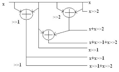
Figure 3. Architecture of shift and add unit.
The multiplexer units are used to select the appropriate output from the shift and add unit. All the multiplexers will share the outputs of the shift and add unit. The inputs to the multiplexers are the 8/4 inputs from the shift and add unit and hence 8:1/4:1 multiplexer units are employed in the architecture. The select signals of the multiplexers are the filter coefficients which are previously stored in a look up table (LUT). The CSM and PSM architectures basically differ in the way filter coefficients are stored in the LUT. In the CSM, the coefficients are directly stored in LUTs without any modification whereas in PSM, the coefficients are stored in a coded format. The number of multiplexers will also be different for PSM and CSM. In CSM, the number of multiplexers will be dependent on the number of groups after the partitioning of the filter coefficient into fixed groups. The number of multiplexers in the PSM is dependent on the number of non-zero operands in the coefficient for the worst case after the application of BCSE algorithm.
The final shifter unit will perform the shifting operation after all the intermediate additions (i.e., intra-coefficient additions) are done. This can be illustrated using the output expression

By coefficient-partitioning [16], obtained value
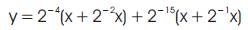
After obtaining the intermediate sums (x + 2-2x) and (x + 2-1x) from the shift and add units with the help of multiplexer unit, the final shifter unit will perform the shift operations 2-4 and 2-15 in (2). The PSM and CSM architectures also differ in the nature of final shifters. In the CSM, the final shifts are constants and hence no PS are required. In the PSM, PS (Programmable Shifter) is used.
This unit will compute the sum of all the intermediate additions 2-4(x + 2-2 x) and 2-15 (x + 2-1x) as in (2). As the filter specifications of different communication standards are different, the coefficients change with the standards. In conventional reconfigurable filters, the new coefficient set corresponding to the filter specification of the new communication standard is loaded in the LUT. Subsequently, the shift and add unit performs a bitwise addition after appropriate shifts. On the contrary, the CSM and PSM architectures perform a binary common subexpression (BCS) - wise addition (instead bitwise addition). Thus, the same hardware architecture can be used for different filter specifications to achieve the necessary reconfigurability. Moreover, the BCS-based shift and add unit reduces addition operations and hence offers hardware complexity reduction. In the next section, the CSM is explained in a detailed manner.
In the CSM architecture, the coefficients are stored directly in the LUT. These coefficients are partitioned into groups of 3-bits and are used as the select signal for the multiplexers. The number of multiplexer units required is [n/3], where n is the wordlength of the filter coefficients. The CSM can be explained with the help of an 8-bit coefficient h = “0.11111111.” This coefficient h is the worst-case 8-bit coefficient since all the bits are nonzero and hence needs a maximum number of additions and shifts. In this case, n = 8, and therefore the number of multiplexers required is 3.The output y = h * x is expressed as

By partitioning into groups of three bits from most significant bit (MSB) (3), obtain value


Note that the terms x + 2-1x + 2-2x and x + 2-1x can be obtained from the shift and add unit. Then by using the three multiplexers (mux), two 8:1 mux for the first two 3-bit groups and one 4:1 mux for the last two bits of the filter coefficients, the intermediate sums shown inside the brackets of (5) can be obtained. The final shifter unit will perform the shift operations 2-1, 2-3, and 2-6. Since these shifts are always constant irrespective of the coefficients, programmable shifters are not required and these shifts can be hardwired. The final adder unit will compute the sum of all the intermediate sumsobtain h * x[n].The architecture of PE for CSM is shown in Figure 4. The coefficient wordlength is considered as 16 bits. The filter coefficients are stored in the LUT in sign-magnitude form with the MSB reserved for the sign bit. The first bit after the sign bit is used to represent the integer part of the coefficient and the remaining 16 bits are used to represent the fractional part of the coefficient. Thus, each 16-bit coefficient is stored as an 18-bit value in LUTs. Each row in LUT corresponds to one coefficient. Note that only half the numbers of coefficients need to be stored as FIR filter coefficients are symmetric. The coefficient values corresponding to 20 to 2-14 are partitioned into groups of three bits and are used as select signals to multiplexers Mux1 to Mux5.i.e., the set (20 , 2-1 , 2-2 ) forms the select signal to Mux1 and so on.

Figure 4. Architecture of PE for CSM
Since there are 3-bits, eight combinations are possible and hence Mux1 to Mux5 are 8:1 multiplexers. The value corresponding to 2-15 forms the select to a 2:1 multiplexer, Mux6. The output from the ith multiplexer is denoted as ri . Note that coefficient with values up to a precision of 16 bits are taken, the shifting of 2-1 is done finally as shown in (4) and (5) and hence the maximum shift will be 2-15 . Mux7 determines whether the output needs to be complemented based on the sign bit of the filter coefficient and hence it is a 2:1 multiplexer.
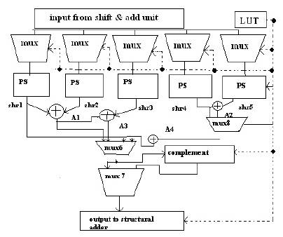
Figure 5. Architecture of PE for PSM
In FIR filters, coefficient values are always less than one. Hence, the integer bits are not employed. However if an integer digit is required, the architectures do not impose any restrictions to accommodate it.
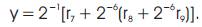
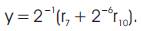
In Figure 4, the shifts are obtained as follows. Let r1 to r6 denotes the outputs of Mux1 to Mux6, respectively. Then

The shifts are obtained by partitioning the 16-bit coefficient into groups of 3-bits.
By partitioning (1)


The expressions from (6)–(10) are represented in Figure 4. The main advantage of the CSM architecture is that all the shifts are constants irrespective of the coefficients and hence can be hardwired resulting in high speed operation of the filter.
The PSM is based on the BCSE algorithm presented in our previous work [5]. The PSM architecture presented in this section incorporates reconfigurability into BCSE. The PSM has a pre-analysis part in which the filter coefficients are analyzed using the BCSE algorithm in [5]. Thus, the redundant computations (additions) are eliminated using the BCSs and the resulting coefficients in a coded format are stored in the LUT. The coding format is explained in the latter part of this section. The shift and add unit is identical for both PSM and CSM. The number of multiplexer units required can be obtained from the filter coefficients after the application of BCSE [5]. The number of multiplexers is selected after considering the number of non-zero operands (BCSs and unpaired bits) in each of the coefficients after the application of the BCSE algorithm. The number of multiplexers will be corresponding to the number of non-zero operands for the worst-case coefficient (worst-case coefficient being defined as coefficient that has the maximum number of non-zero operands). The architecture of PE for PSM is shown in Figure5. The coefficient wordlength is fixed as 16 bits. The number of multiplexers are fixed as 5 (same as the number of non-zero operand). The LUT consists of two rows of 18 bits for each coefficient of the form SDDDDXXDDDDXXMMMML and DDDDXXDDDDXXDDDDXX, where “S” represents the sign bit, “DDDD” represents the shift values from 20 to 2-15 and “XX” represents the input “x” or the BCSs obtained from the shift and add unit. In the coded format, XX = “01” represents “x,” “10” represents x+2-1x, “11” represents x + 2-2x, and “00” represents x + 2-1x + 2-2x, respectively. Thus, the two rows can store up to five operands which is the worst case number of operands for a 16-bit coefficient. In most of the practical coefficients, the number of operands is less than the worst case number of operands, 5. In that case “MMMML” can be used to avoid unnecessary additions. The values “MMMM” will be given as select signal to the Mux6 and “L” to Mux8. “MMMML” indicates the presence of five operands. A “1” in each position indicates the presence of each operand. Thus, for all operands to be present will be indicated by “MMMML” = “11111.” This means the Mux6 will select the output from the output of adder, A4 and Mux8 will select the output of adder, A2. If only first operand is present, “MMMML” = “10 000.” This means the Mux8 will select the output of PS, shr4 and Mux6 will select the output of PS, shr1.
As a result of this none of the adders shr1 to shr4 will be loaded saving significant amount of dynamic power. The coding can be explained as given blow.
Consider the positive coefficient h
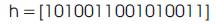

Then (12) will be stored in the LUT as 000001101011011110 &100111111010000000. It must be noted that as (12) has only four operands, the fifth operand values “DDDDXX” are substituted as 000000 and “MMMML” as “11110.” The XX values are given as select signals for Mux1 to Mux5. The values of DDDD are fed to corresponding PS. The multiplexer Mux6 and Mux8 will select the appropriate output in case the number of operands after BCSE is less than 5. The use of Mux6 and Mux8 reduces the number of adders utilized by selecting the output from the appropriate adder as all the adders in the PE are not always needed. For example, in (12), as only four operands occur, output can be taken from the output of PS, shr4 without using adder, shr2. Mux8 will do this and hence the adder shr2 is not loaded and consumes zero current and power. The select signals of Mux6 and Mux8 have five bits and hence 25 different control signals are possible which adds lots of flexibility to the architecture which can be employed in future if required. Mux7 is used to complement the output in case of a negative coefficient and its select signal is the sign bit “S” of the coefficient. The PSM architecture has two advantages; first, it guarantees a reduced number of additions compared to CSM, and second it offers the flexibility of changing the wordlength of coefficients. The same PSM architecture designed for 16-bit coefficients is capable of operating for any coefficient wordlength less than 16 bits. This means, if the wordlength is reduced, the format of the LUT can be changed if required. The main advantage of reducing the precision is that some of the adders in the PSM architecture will be unloaded resulting in zero dynamic power. To the best of our knowledge, the PSM architecture is the first approach toward programmable coefficient wordlength FIR filter architecture. This means that the coefficient wordlength of the PSM architecture can be changed dynamically without any change in hardware.
In this section, the synthesis and design results of the CSM and PSM architectures are compared.System behavior is verified via simulation using Modelsim SE 5.7g. The simulators are used to simulate the Hardware models. The waveform output is obtained from the simulator to see if the DUT (Device Under Test) is functionally correct. The major three parameters like area, delay and power of both architecture CSM and PSM are compared using Xilinx. Integrated Software Environment (ISE) 8.1 tool For Performing Synthesis of the designs.
The five adders and three adders are used in conventional & BCSs based shift & add unit respectively. Hence by using BCSs based shift & add unit the number of adders are reduced (Figures 6,7,8 & 9).

Figure 6. Simulation Waveform for Conventional Shift & Add Uni
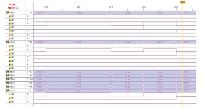
Figure 7. Simulation waveform for BCS based Shift & Add unit
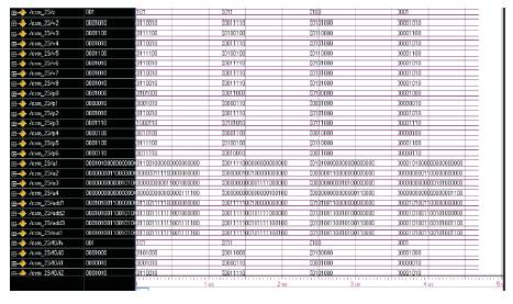
Figure 8. Simulation waveform for Architecture of PE for CSM Architecture

Figure 9. Simulation waveform for Architecture of PE for PSM Architecture
Comparison of CSM and PSM for major three parameters (Area, Delay, Power) are given in Figures 10,11 & 12. The parameters are compared using the Xilinx ISE 8.1 tool which shows that the PSM architecture has reduced number of gate count & amount of power compared to CSM architecture. But the delay is low for CSM architecture compared to the PSM architecture.

Figure 10. Comparison of Gate Count For CSM & PSM

Figure 11. Comparison of Delay For CSM & PSM
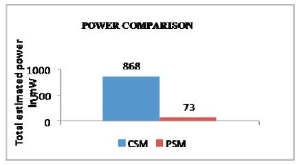
Figure 12. Comparison of Power For CSM & PSM
Two new approaches namely, CSM and PSM are for designing reconfigurable higher order filters with low complexity. The CSM architecture results in high speed filters and PSM architecture results in low area and thus low power filter designed. The PSM also provides the flexibility of changing the filter coefficient wordlengths dynamically. These methods are based on the binary common subexpression elimination (BCSE) algorithm using canonical signed digit (CSD) representation of coefficients. The CSD representation is widely used in implementing multiple constant multiplication because it guarantees the least number of additions for a given constant multiplication. If the filter coefficients are based on minimal signed digit (MSD) representation which is more appropriate in finding common subexpressions for multiple constants, the number of adders required for the filter design are significantly reduced.