Power MOSFET in Automobile Application
This paper focuses on the simulation Power MOSFET inverter driving the electrical motors such as PMBLM used in automotive power electronic systems to ensure energy efficiency. Today Power MOSFETs are available with high voltage, high power, high frequency. protection against avalanche and short circuit behavior. Control techniques such as Six- Step, SPWM, SVPWM are used for simulation and advantages of the drive are confirmed with the simulation results.
Power Electronic System provides the basis for EV with important aspects such as required electrical energy conversion, high power handling capability, easy control with high switching frequency and capable of driving electric motors with high speed. Power MOSFETS are widely used in automotive power electronic systems and often determine the efficiency, cost and size of the system. These Power MOSFET switch should have characteristics i) low drain resistance Rds and Conduct large current in ON mode, ii) high reverse breakdown voltage Vbr and high power handling capability, iii) Fast ON and OFF switching without switching losses, iv) protection against avalanche and short circuit beheviour and v) Rugged and reliable.
In switching mode power converter, a Power MOSFET generates conduction and switching losses. Conduction losses are caused by Rds and switching losses are caused by interelectrode capacitances. While designing Power MOSFETs drain resistance Rds and reveres voltage Vbr should be considered. Increase in reverse blocking capability also increases the drain resistance Rds which correspondingly decreases the drain current ID For this. Power MOSFET's construction should be changed which affects manufactures cost of Power MOSFET. Today combination of technologies improves reduction in Rds by a factor of five, increase in break down voltage, reduction in size mainly thickness and thermal impedance between epi layer and packaging. For Example Mdmesh, CoolMOS [1].
A Power MOSFET is fabricated from several parallel connected cells organized in various geometrical design. A single MOSFET cell is made up of four semiconductor layers: the n+ -n- -p –n+ as shown in Figure1. The parasitic capacitances shown in Figure 1 are Cgs, Cgd and Cds determines the switching behavior of Power MOSFET.
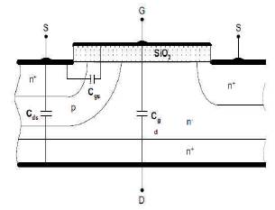
Figure 1. Structure of VDMOS Power MOSFET
CoolMOS Power MOSFET shown in Figure 2 developed by Infineon Technologies [2] shows improvement in Rds by a factor of five and also the high breakdown voltage Vbr with conventional 600V Power MOSFET. CoolMOS™ technology employed a novel internal structure that offered low on resistance with a completely altered voltage dependence of device capacitances. This gives an almost linear relationship between the specific on resistance Rds and the maximum blocking capability Vbr of the transistor. Decrease in Rds reduces the conduction losses and increases the current capability of the device. The new generation CoolMOS also improves ruggedness aspects such as avalanche and short circuit behavior and reach the limit of active zener clamped devices. CoolMOS diode shows low reverse recovery time TRR, low reverse recovery current IRR and hence fast turn off than conventional MOSFET.
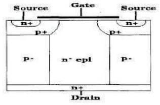
Figure 2. Structure of CoolMOS Power MOSFET
Capacitance Cgs, Cgd and Cds of CoolMOS transistor have lower values than a conventional MOSFET at the same Vds. The capacitance Cgd lower the gate charge Qgd in particular and hence the lower the switching losses [3]. The drastic reduction in the gate charge in the new CoolMOS technology is very beneficial when driving the device. As a result, a CoolMOS transistor can be operated with the lowest control power, the cheapest driver circuit and the highest switching frequencies. Therefore CoolMOS transistors are superior to conventional power MOSFETs at both low and high switching frequencies. So CoolMOS power MOSFETs fulfill the performance requirement for EV.
The purpose of this paper is to study electronic control of EV using Power MOSFETs in automobile application.
The block diagram of EV shown in Figure 3 is popular in automobile applications [4]. The main components of EV are (i) Batteries as electrical source, (ii) Inverter, (iii) PMBL Motor (BLDCM& PMSM) and (iv) PWM Control.
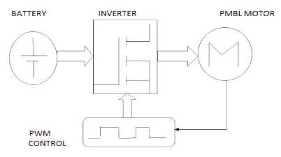
Figure 3. The Block Diagram of EV
EV needs fast charge and deep cycle batteries which have a certain power capacity but more important is a considerable energy content. The battery capacity was selected based on the observations that the mass of a battery is proportional to its energy content. To obtain higher dc bus voltage stack of battery is used i.e. series and parallel combination of many batteries are required.
For EV mainly two types of circuits are used. They are Choppers and Inverters. Chopper circuit uses dc to dc conversion while Inverter uses dc to ac conversion. The three phase bridge inverters are used for high power application. Three single phase half bridge inverter are connected in parallel with star type inductive load. The gating signals of single phase inverters should be delayed by 120 degree with respect to each other to obtained balanced fundamental voltages.
Requirement for EV are light weight, wide speed range, high efficiency, maximum torque and long life. Battery operated drives must make optimum use of the energy stored in the battery. To do this, the efficiency of both motor and drive are critically important. The efficiency of the motor is low at low speed, in overcoming armature inertia, and again at high speed as heating of the winding absorbs input power. Different machines are used for EV. Popular are DC motors, Induction motors and PMBL Motor. PMBL Motor have Low noise, high efficiency(due to absence of field coil losses), no reduction of excitation requirement, ease of control, lighter, ease in cooling.
PMBL Motor have important advantages over brushed DC motor and Induction motor namely lightweight, better speed/torque characteristics, high efficiency and high dynamic response, are compact, need lesser maintenance. PMBL Motor has edge over DC motors and induction motor in terms of weight/size, efficiency and inverter because it operates with leading power factor under constant power condition. Permanent Magnet Machines are due to their high efficiency, power density, and torque to inertia ratio a common choice in EV. PMSM are depending on the supply voltage waveform divided into BLDC which are fed with trapezoidal voltage wave form and PMSM are fed with sinusoidal waveforms. However, in the present work the scope is limited to only PMSM with sinusoidal waveforms. They contribute significantly to improve the overall efficiency of the vehicle.
PMSM machine consist of a polyphase, rotating field stator, a permanent magnet rotor and a rotor position sensor which is shown in Figure 4.
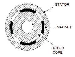
Figure 4. Construction of PMSM
The three phase star connected PMSM can be described by the following equations [5-6].These equations are obtained from three phase model of PMSM as shown in Figure 5.
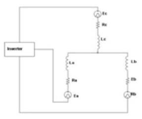
Figure 5. Three-Phase Model of PMSM
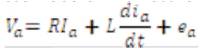
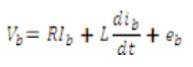
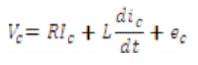
Where V,I and e are the voltage, current and back emf of phases a,b and c; R and L are resistance and inductance of each phase respectively.
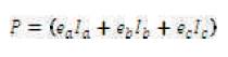
Torque Te related with rotor peed w and power P is given by
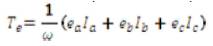

Where
PMSM operated in two modes; i) torque control and ii) speed control. In torque control mode torque is directly proportional to the motor current while in speed control mode speed is directly proportional to the applied voltage across its winding.
In EV the voltage source inverter VSI is much popular. In VSI, the relationship between DC voltage and ac line to line rms voltage varies, depending on the modulation strategies. There are three different control strategies for the control of three phase AC output voltage of PMSM are Six Step control, SPWM and SVPWM.
In automotive electric drives the VSI is much popular. In VSI, the relationship between DC voltage and AC line to line rms voltage varies, depending on the modulation strategies. There are three different strategies for the control of three phase AC output voltage, i.e. Six Step control, SPWM and SVPWM.
In the Six Step Rectangular Waveform control, three switches are ON and OFF in each time interval, (612,123, 234, 345, 456, 561 and back 612). The AC line to line fundamental voltage can be given as:
The magnitude of the fundamental phase voltage with six step control is (2/π) VDC . A high AC voltage can be achived at the given DC voltages. The higher voltage leads to lower resistance losses, since the current is relatively low due to high voltage at given power output. Howevever the low order harmonics, such as 5th and 7th appear in voltage waveforms, which causes high stray losses of the machine.
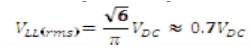
When the variation of the switching duty cycle is sinusoidal, an approximately sinusoidal phase current can be obtained. This modulation strategy is called Sinusoidal PWM strategy. With SPWM strategy, the rms value of the AC line–to-line fundamental voltage can be obtained as follows:
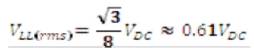
The magnitude of AC fundamental voltage is 1/2(VDC) with SPWM. Absence of Lower harmonic voltage and current is the main advantages, which helps to reduce the stray losses of the machine. On the other hand, its AC output voltage is lower than that six-step control, which will increase the resistance losses due to higher AC current for the same output power requirement. Compared to sixstep control, further, the chopping frequency is high in SPWM, which causes inverter losses. To increase the output AC voltage at given DC bus voltage, the SVPWM can be used without introducing much harmonic components. With SVPWM control, the rms value of the AC fundamental voltage can be achieved as:
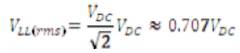
The magnitude of AC fundamental voltage is  (VDC) with SVPWM. Actually the AC output voltage increases by 15% in the SVPWM, compared to the SPWM. Note that changing the control strategy between SVPWM and Six-Step control can increase the speed varying ratio of the motor.
The three phase inverter which is driving three phase PMSM simulated using Matlab software. The simulation is performed under conditions: Supply voltage Vdc=400V, switching frequency fs =1kHz and PMSM (Ra =1.6Ω, La=6.4μH, Pole Pair =2, Flux Linkage =0.1852, Torque =3Nm; Speed ω = 4250RPM). The simulated output waveforms and corresponding FFTs of motor phase current and phase voltage for Six Step control ,SPWM and SVPWM are as follows.
Figure 6 shows motor phase current I and corresponding a FFT at inverter frequency fo = 60Hz and modulation index M=.9 while Figure 7 shows motor line voltage Vab and corresponding FFT at inverter frequency fo = 60Hz and modulation index M=.9. The motor phase current Ia has low distortion as compared to motor line voltage Vab. The shape of motor phase current waveform Ia is not exactly sinusoidal.
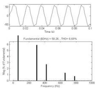
Figure 6. Six Step Waveform of Phase Current Ia and FFT of Phase Current Ia.
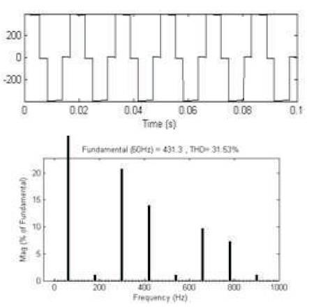
Figure 7. PWM Waveform of Line Voltage Vab and FFT of Line Voltage Vab
Figure 8 shows motor phase current I and corresponding a FFT at inverter frequency fo = 60Hz and modulation index M=.9 while Figure 9 shows motor line voltage Vab and corresponding FFT at inverter frequency fo= 60Hz and modulation index M=.9. The motor phase current Ia has low distortion as compared to motor line voltage Vab. The shape of motor phase current waveform Ia is sinusoidal.
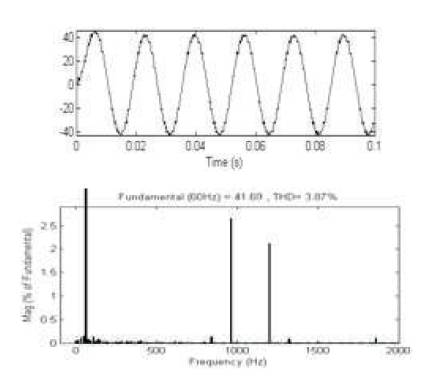
Figure 8. SPWM Waveform of Phase Current Ia and FFT of Phase Current Ia.
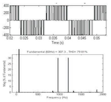
Figure 9. SPWM Waveform of Line Voltage Vab and FFT of Line Voltage Vab
Figure 10 shows motor phase current I and a corresponding FFT at inverter frequency fo = 60Hz and modulation index M=.9 while Figure 11 shows motor phase voltage Vab and corresponding FFT at inverter frequency fo = 60Hz and modulation index M=.9.The motor phase current Ia has low distortion as compared to motor phase voltage Vab. The shape of motor phase current waveform Ia is sinusoidal.
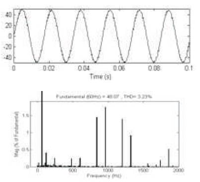
Figure 10. SPWM Waveforms of Phase Current Ia and FFT of Phase Current Ia
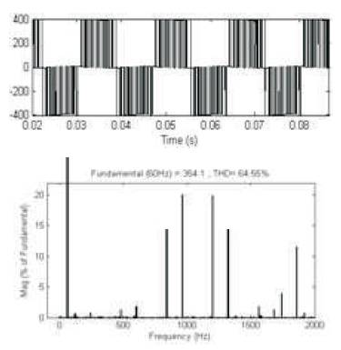
Figure 11. SVPWM Waveforms of Line Voltage Vab and FFT of Line Voltage Vab
Values of fundamental component of phase currents and phase voltages of BLDC Motor with their THD are reported in Table 1.
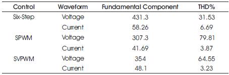
Table 1. Fundamental Component & THD for Six Step, SPWM,SVPWM control
In order to determine the efficiency of the EV system, it is essential to obtain the fundamental component of motor current and corresponding THD. The fundamental component of motor current responsible for driving the motor and the THD determines the losses and degraded the efficiency. So higher is the fundamental component of motor current, lower is the THD the higher will be the Efficiency. The SVPWM inverter offer 15% increase in output voltage than SPWM inverter. Also SVPWM inverter provide less THD than SPWM inverter and Six-Step inverter. Constant torque operation is used for Six- Step, SPWM and SVPWM control.