Voltage instability is a state of power system encountering an unacceptable voltage level. This paper describes the expressions of Fast Voltage Stability Index (FVSI) and Line Quality Factor (LQF), which may be considered as indication of voltage collapse under constrained condition of an interconnected power system. Artificial Neural Network Technique has been applied to identify the voltage collapse condition. The novelty of this method is that, once the ANN model of the system is developed, through on line checking of the load of the weak bus, the present method can immediately calculate the FVSI and LQF without going through the complex classical calculations. The developed ANN technique has been tested in IEEE 30 bus test system and is found to be in excellent agreement with the result obtained by classical method.
The continuous increase in demand for electric power has resulted in an increasingly complex interconnected system, forced to operate closer to the limit of stability. Voltage instability is characterized by the inability of the system to retain its voltage near the nominal value, even with a change in connected susceptance at the load bus. In a multibus interconnected system, if load (active and/or reactive) increases continuously the voltage of each bus decreases. From this condition, different voltage stability limits may be obtained. Researches are going for long to study voltage instability of an interconnected power system [1], [2], [3] A review of literature reveals that, researchers have been trying to investigate the static aspect of load flow solutions by applying various methods for identifications of the point of bifurcation and to estimate the stability margin of the system. [4], [5], [6 ANNs have attracted the great deal of attention because of their pattern recognition capability and their ability to handle corrupted data. They have been successfully applied in certain power engineering problems. [7], [8]. ANN has the ability to solve the problems with high non-linearity such as system security and stability assessment. [9], [10]. An ANN is programmed, by presenting it with a training set of input-output patterns from which, it learns the relationship between them. Its ability to perform is well affected by the chosen training data as well as network topology and training scheme.
This paper focuses on two different methods of stability indices. Computer simulation has been conducted to calculate the stability indices on IEEE 30 bus test system considering different loading conditions after detecting the degree of weakness of load buses. The proposed ANN model is then trained to correlate the voltage stability status of the system with changing load pattern. A comparison of the results obtained by ANN model with classical calculation, has been presented in the text to point out the efficiency of ANN based technique in predicting of voltage collapse condition.
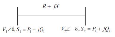
An interconnected system is reduced to a single line network and applied to assess the overall system stability. Utilizing the same concept but using it for each line of the network stability criteria can be developed. Consider a single line of an interconnected network shown in Figure 1. The line is connected to other lines forming a grid network. Any of the lines from that network can be represented with the following parameters shown in Figure 1.
Figure 1. Typical one line Diagram of Transmission line
The sending end bus voltage is actually the summation of line drop and receiving end voltage [11]
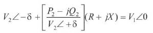
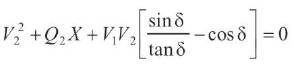
from equation(1), after separating the real and imaginary part and eliminating S we can have the following equation
To have real solutions for voltage equation (2) must have real roots. Thus the following conditions, which can be used as stability criterion, need to be satisfied:
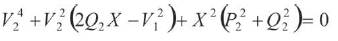
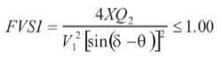
from equation (1), the real and reactive parts are separated value of P2 is obtained from real part and substituted in reactive part to get
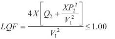
For getting real solution of voltage, equation (4) should have real roots and at limiting condition the following criterion must be satisfied:
The stability criteria equation (3) and (5) are used to find the stability index for each line connected between two busbars in an interconnected power network. Based on the stability indices of the lines, voltage collapse can be accurately predicted. As long as the stability indices are less than 1, the system is stable and when these exceed the value 1, the whole system loses its stability and voltage collapse occurs.
The Feed Forward Neural Network (FFNN) is characterized as having a layered architecture where a layer is composed of units or nodes that are connected to other nodes using a certain connection topology. A node describes a single mathematical function that operates on the summation of all the inputs to the node as shown in Figure 2. The function chosen is nonlinear to provide the ANN with the ability to model nonlinear relationships. The interconnection between each pair of nodes has an associated multiplier (weight). The network is further characterized by a propagation and training rule. The propagation of inputs applied to the input layer to obtain outputs of the output layers follows a forward path through the weights and nodes. Thus the network is presented with the training data, which consists of input and output pairs. For each input and output pair, the algorithm adjusts the weights to minimize the error between desired and calculated output. In this manner the entire training data is repeatedly presented until the overall error has reached the desired tolerance.
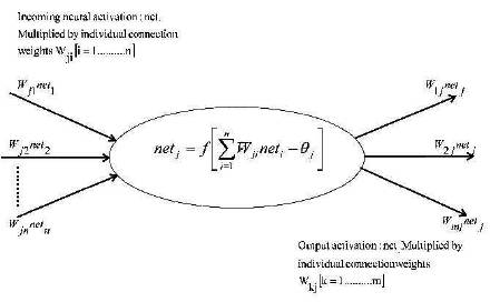
Figure 2. Characteristics of a Node of ANN
Units are connected to one another. Connections correspond to the edges of the underlying directed graph. There is a real number associated with each connection, which is called the weight of the connection. We denote by Wij the weight of the connection from unit ui to unit uj. It is then convenient to represent the pattern of connectivity in the network by a weight matrix W whose elements are the weights Wij. Two types of connection are usually distinguished: excitatory and inhibitory. A positive weight represents an excitatory connection whereas a negative weight represents an inhibitory connection. The pattern of connectivity characterises the architecture of the network (Figure 3).
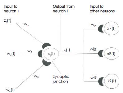
Figure 3. A unit in the output layer Determines its activity by following a two step procedure
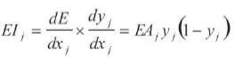
First, it computes the total weighted input xj, using the formula:
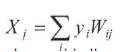
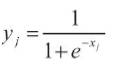
where yi is the activity level of the jth unit in the previous layer and Wij is the weight of the connection between the ith and the jth unit. Next, the unit calculates the activity yj using some function of the total weighted input. Typically we use the sigmoid function:
Once the activities of all output units have been determined, the network computes the error E, which is defined by the expression:
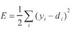
where yj is the activity level of the jth unit in the top layer and dj is the desired output of the jth unit.
The algorithm consists of four steps:
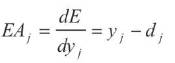
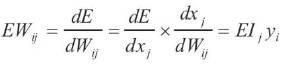
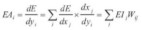
By using steps 2 and 4, we can convert the EAs of one layer of units into EAs for the previous layer. This procedure can be repeated to get the EAs for as many previous layers as desired. Once we know the EA of a unit, we can use steps 2 and 3 to compute the EWs on its incoming connections.
The IEEE 30 bus test system (Figure 4) has been used for simulation purpose. In this system, bus number 26 has been found to be weakest followed by bus number 30 and 29. However bus number 26 has only one interconnecting line with the rest of the system and a contingency of this line will cause complete isolation of bus number 26. Hence second weakest bus i.e. bus number 30 has been considered and its impact on steady state voltage stability has been observed. For different load values at bus number 30, the developed ANN algorithm is able to find out the stability limit for the system without any classical calculation.
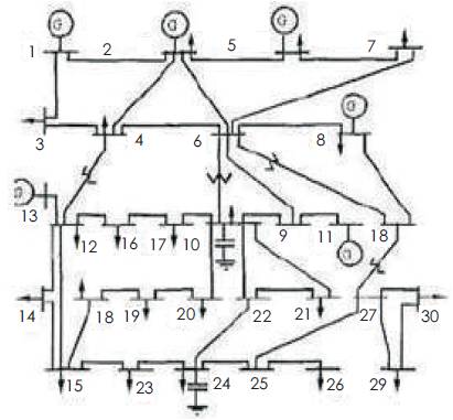
Figure 4. IEEE 30 bus System
The ANN model was trained with a number of input training vector set to meet convergence criterion. After the training goal is achieved and the network is fully trained with the correlation between the changing load pattern and the corresponding values of FVSI and LQF for the lines connected with the bus number 30, i.e. line connected with bus 30 and 27 and line connected with bus number 30 and 29. The generalizing capability of the trained ANN model is tested by a set of unknown test data. A few sample of the test results are in Table I. The agreement between computed and estimated results is good.
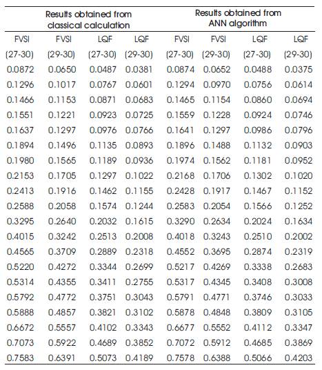
Table 1. Comparison of Results
This paper presents an ANN based technique for determination of voltage stability status in a multibus power system. At first analysis based on MATLAB software has been done. Then ANN based system has been designed which are trained by some data available from previous analysis. A case study has been conducted on IEEE 30 bus network and the result obtained clearly indicate the proposed method that can be efficiently used for on line assessment of voltage stability under normal as well as heavily loaded conditions to achieve improved voltage stability of the power network.