Figure 1. Flattened and Dimpled Sinusoid Waveform
A new filter strategy for harmonic elimination is introduced in this paper. The proposed filter eliminate undesirable harmonic from periodic signal. The proposed approach eliminates all harmonics component from periodic signal and it requires only knowledge of the frequency of the fundamental component. Adaptation process adjusts weights to exactly match amplitude and phase of fundamental frequency component and the outputs of the filter is a harmonics replica and are subtracted from the original composite waveform to eliminate them. The bipolar waveforms are roughly analyzed. The simulation results shows that the method can effectively eliminate undesirable harmonics and result in low(less than one percentage) total harmonic distortion (THD).
A single-phase square wave inverter has the least desirable output waveform type; a square wave, [1] is sort of a "flattened-out" version of a sine wave. Generally, square wave output inverter available in market is simple in design and low cost. Such inverter has some disadvantages. For starters, the peak voltage of a square wave is substantially lower than the peak voltage of a sine wave. In addition, a square wave contains many higher frequencies as well, called harmonics, which can cause buzzing or other problems. A harmonic is a signal or wave whose frequency is an integral (whole-number) multiple of the frequency of some reference signal or wave[2]. For a signal whose fundamental frequency is f, the second harmonic has a frequency 2f; the third harmonic has frequency of 3f, and so on. Signal occurring at frequencies of 2f, 4f, 6f, etc. are called even harmonics; the frequencies 3f, 5f, 7f etc. are called odd harmonics. If all the energy in a signal is contained at the fundamental frequency, then that signal is a perfect sin wave. If the signal is not a perfect sine wave, then some energy is contained in the harmonics. Examples are square wave, saw tooth wave and triangular wave. It is well know that any periodic waveform such as that mentioned previously can be represented by Fourier series, an infinite sequence of sine and cosine waves, at the fundamental frequency of the waveforms and its harmonics. These harmonics can cause trouble in several areas particularly in motors and sensitive application. The coefficients of the Fourier series are computed with a pair of integral's that produces the coefficients of the sine and cosine terms in series. For a signal f(x) with a zero dc component, the integrals are
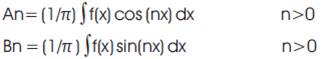
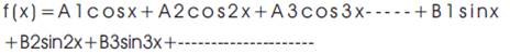
where the An and Bn terms are the coefficients of the cosine and sine terms, respectively, in the series. The Fourier series is then:
In conventional square wave have both half-wave symmetry and quarter-wave symmetry, integration is required only over one-quarter of the waveform, and further that only the sine terms and odd harmonics are required. Thus, the integral used to compute the coefficients for the conventional square wave becomes
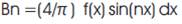
(4/n π) for odd values of n only.
The series is then (4/ π) sin(x) +(4/3 π ) sin(3x)+ (4/5 π sin(5x)+------
The standard measure for distortion is Total Harmonic Distortion (THD). Numerical evaluation of the coefficient for the square wave indicates that if the square wave is to be considered a sine wave with distortion, the THD is in the range of 45%.
A Novel method for selective Harmonic Elimination is described in [3]. Another method to eliminate harmonics in single-phase PWM inverter is highlighted in [4]. In paper [5] Harmonic voltage reduction using a series Active filter under different load conditions is described. The main challenge is associated with elimination of all harmonics. This manuscript proposes On approach for harmonic elimination based an adaptive filter technology is developed. The task is accomplished by generating harmonics replica using fundamental frequency of composite signal. The output of adaptive filter is a harmonics replica and is subtracted from the composite signal of fundamental frequency to eliminate them and the total harmonic distortion (THD) is greatly reduced. The weights of filter are adjusted on-line by using LMS/RLS adaptive filtering algorithm. The above course is used as a basis for the development of adaptive harmonics elimination algorithm. From the comparison result, it is seen clearly that this method has better harmonic elimination efficiency and faster weight convergence.
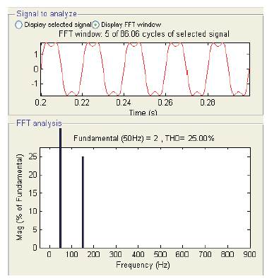
Harmonics are AC voltages and currents with frequencies that are integer multiples of fundamental frequency. On a 50Hz system, this could include 2nd order harmonic (100Hz), 3rd order harmonic (150Hz), 4th order harmonics (200Hz), and so on.
The flattened and dimpled sinusoid in Figure1 has the mathematical equation y=2sin (2π50) +0.5sin (3*2π 50). This means a 50Hz sinusoid(the fundamental frequency) added to a second sinusoid with a frequency three times greater than the fundamental (150Hz) and an amplitude ¼(0.5times) of the fundamental frequency.
Figure 1. Flattened and Dimpled Sinusoid Waveform
Similarly the peaky sinusoid in Figure 2 has the mathematical equation y=2sin (2π50)-0.5sin (3*2π50). This waveform has the same composition as the first waveform except the third harmonics component is out of phase with the fundamental frequency, as indicated by the negative sign preceding the “0.5sin(3*2π50)”term. The waveform in Figure 3 contains third, fifth, seven, nine and eleven harmonics in phase with the fundamental frequency. The waveform in Figure 4 contains several other harmonics in addition to the second harmonic some are in phase with the fundamental frequency and others out of phase.
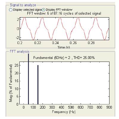
Figure 2. Peaky Sinusoid Waveform
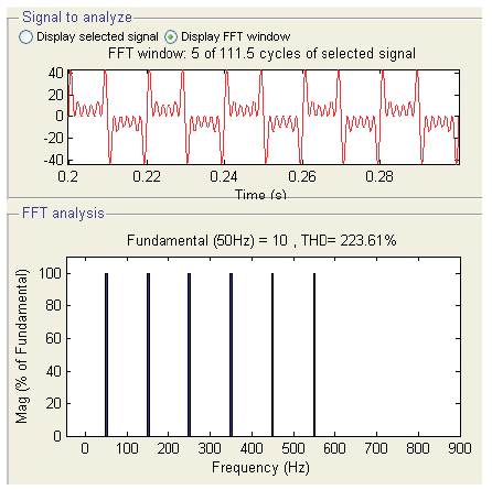
Figure 3. The wave contains third, fifth, seven, nine and eleven harmonics
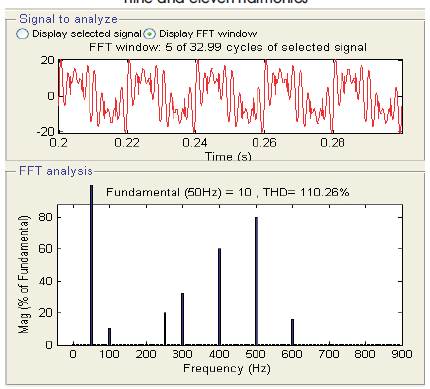
Figure 4. Contain Several Other Harmonics in Addition to the Second Harmonic
As the harmonic spectrum becomes richer in harmonics the waveform takes on more complex appearance, indicating more deviation from the ideal sinusoid. A rich harmonic spectrum may completely obscure the fundamental frequency sinusoid, making a sine wave unrecognizable. When the magnitude and order of harmonics are known, reconstructing distorted waveform is simple.
Decomposing a distorted waveform into its harmonic component is considerably more difficult. This process requires, Fourier analysis, which involves a fair amount of calculus. However, electronic equipment has been developed to perform this analysis on a real time basis. One of the strategies is to reduce the magnitude of the harmonic waveform, usually by RC and LC filtering. Simple two RC pair low pass filter can be used for filtering the harmonics as shown in Figure 5, Resultant input and output of RC filter are shown in Figure 6.The output contain fundamental frequency component of amplitude 0.005598V instead of 12.73V and output is load dependent.
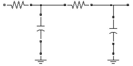
Figure 5. RC Filter
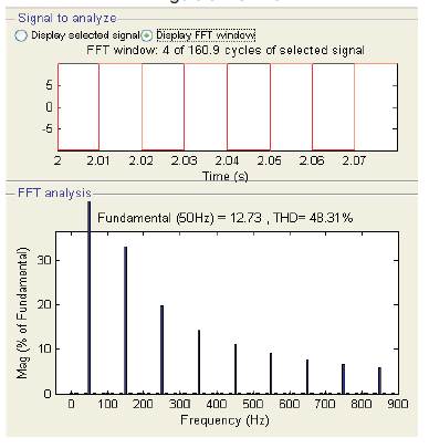
Figure 6 (a) Performance of RC filter: Output Waveform without filter for 10V, 50Hz
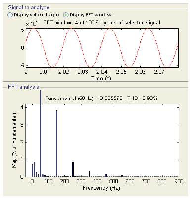
Figure 6. Performance of RC filter: (b) Output Waveform with filter for 10V, 50Hz
LC low pass filter can be used for filtering the harmonics as shown in Figure 7, Resultant output of LC filter shown in Figure 8 contain fundamental frequency component of amplitude 12.42 instead of 12.73 and output is load dependent and unstable. The other method is to use system components that can handle the harmonics more effectively, such as K-factor transformers. Harmonic filters can be constructed by adding an inductance (L) in series with a power factor correction capacitor(C). The series L-C circuit can be tuned for a frequency close to that of the troublesome harmonic, which is often the 5th by tuning the filter in this way, you can attenuate the unwanted harmonic. This can be a very cost effective means of reducing harmonics. Because of the computation difficulty of the resultant method to eliminate all harmonics an approach is proposed using RLS and LMS Algorithm.
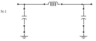
Figure 7. LC Filter
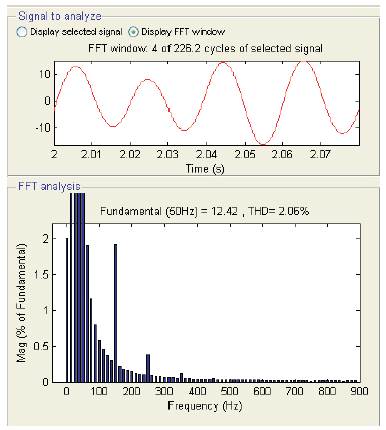
Figure 8. Performance of LC filter: Output Waveform with filter for 10V, 50Hz
Elimination of an undesirable harmonic component from a signal can be done by proposed approach. The circuit consists of a summing point and recursive least square (RLS)/ a least mean square (LMS) adaptation Algorithm. It operates in the following way:
The RLS adaptation algorithm as developed in [6] will discussed as
Steps in calculation of filter coefficients are
 (n-1)w(n)(n)= (n-1)+k(n)e*(n)
The RLS algorithm uses the information contained in all the previous input data to estimate the inverse of the autocorrelation matrix of the input vector. It uses this estimate to properly adjust the tap weights of the filter. In the above equation, P corresponds to the inverse of the autocorrelation matrix of the input; K is a quantity called the gain vector. Lambda is the forgetting factor, which tells the filter to forget earlier inputs. Conventional LMS algorithm[7] is an important member of the family of stochastic gradient algorithms. It minimizes the mean square error to yield the optimum filter coefficients. The LMS algorithm is a linear adaptive filtering algorithm. It consists of two basic processes.
Where, N= no. of filter taps, n=0, 1, 2, ------M
M=length of input sequence
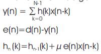
y(n)=output of equalizer
h(n)=equalizer impulse response
e(n)=error sequence
x(n)=input sequence
μ=step size parameter, it control the rate of convergence of the algorithm to the optimum solution. Large value of μ leads to large step size adjustments and thus rapid convergence, while a small value of μ results in slower convergence. However, if μ is made too large the algorithm becomes unstable. To ensure stability μ must be chosen to be in the range, 0< μ<2/NSmax , where Smax is the maximum value of the power spectral density of the input sequence. In general, it seems to converge within 2N iteration, this is well over an order of magnitude increase in performance versus LMS algorithm. RLS algorithm has significantly faster convergence behavior than LMS algorithm. For the RLS algorithm the behavior of the filter coefficients is much more stable. They adhere much closer to the correct values.
A new approach is proposed in this paper to eliminate all harmonics from square wave waveform. A square wave output waveform which contain many odd harmonics (ex.3rd , 5th , 7th etc.) First, a fundamental frequency of square wave is applied to LMS/RLS algorithm and LMS/RLS adaptive filter gives output of harmonics replica present in square wave output wave. Next, harmonics replica is subtracted from square wave output. Therefore, the output voltage wave is sinusoidal waveform of fundamental frequency. The proposed scheme is validated under no load condition. Input and output waveforms are shown in Figure 9 using MATLAB/Simulink. As compared to LMS algorithm RLS algorithm gives better response: low THD (0.03%) and amplitude of fundamental frequency component equal to 15.28V. Table 1 gives the performance parameters at various load conditions.
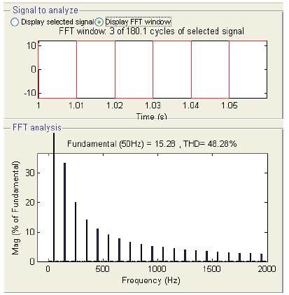
Figure 9. Performance of the Proposed Scheme: (a) Output Waveform Without Filter for 12V, 50Hz
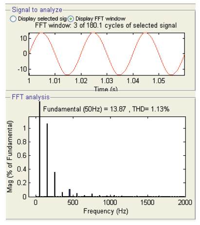
Figure 9. Performance of the Proposed Scheme: (b) Performance of Adaptive Filter using LMS Algorithm: Output Waveform with Filter for 12V, 50Hz
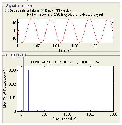
Figure 9. Performance of the Proposed Scheme: (c) Performance of Adaptive Filter using RLS algorithm: Output Waveform with Filter for 12V, 50Hz
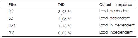
Table 1. Performance Parameter at Various Load Conditions
A novel method has been proposed and developed to eliminate undesirable harmonics from composite signal using LMS/RLS algorithm. The simulation results show that the proposed filter can be used to eliminate higher order harmonics effectively. The simulation result show that the method can effectively eliminate all odd harmonics from square wave and sine wave is produced with total harmonic distortion less than one percentage. The advantages of this approach are simple design, low THD and cost effective.