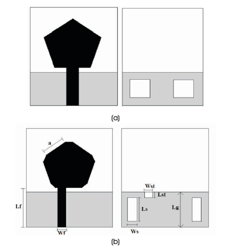
Figure 1. (a) Classical Antenna, (b) Proposed Antenna with Front and Back View
This paper presents a compact pentagon shaped monopole microstrip patch antenna, which has been modified to improve its performance. All sides of pentagon patch are truncated and offset feeding is provided to enhance the bandwidth. Defected Ground Structure (DGS) is used which has two rectangular slots of quarter wavelength opposite to each other, and a notch beneath the feedline on the partial ground plane. These slots on the ground plane improves the gain and return loss of the design. The analysis is performed and results are obtained using Ansoft High Frequency Structure Simulator (HFSS). Various parameters which include impedance bandwidth, gain, efficiency, radiation pattern and current distribution of the antenna are studied. The performance of proposed antenna is compared with classical antenna design, both having same operating frequency of 7.4 GHz. Results obtained from the simulation shows impedance bandwidth of 16.65 (3.85-20.5 GHz) GHz, which is 60% enhanced bandwidth as compared to classical antenna, maximum gain of 6.85 dB at 14.35 GHz, peak return loss of -41.6 dB at 7.2 Ghz and good radiation pattern is observed at frequencies of 7.34, 10.4, and 19 GHz. Application of this antenna covers Ultrawide Band (UWB), X Band and Ku Band, and it can be used efficiently for mobile or satellite communication.
Microstrip Antennas (MSA) are one of the most used antennas for various Global Positioning System (GPS), mobile, radio and satellite applications. They offer features with simplicity and attractive structure providing wideband range of operation and omni-directional radiation patterns in a very compact size (Constantine, 2005) . They are conformable to any planar or non-planar structure and inexpensive in fabrication using advanced printing technologies (Constantine, 2005) . With advancement in technology and increase in number of users, it becomes difficult to optimize the capacity and quality coverage, thus arises the need of broad banding, miniaturization in size and compatibility for integration (Gadhafi et al., 2016 Nahata and Bhagat., 2014) ; .
There are few disadvantages possessed by MSA such as low bandwidth, low gain, high Q factor and spurious feed radiation (Constantine, 2005) . Number of methods are applied in the designs to improve these factors. Different shapes of radiators are designed according to the application of antenna (Lin et al., 2005a; Nahata and Bhagat., 2014; Sayidmarie and Fadhel, 2012). The rectangular and circular patches are most widely used due to high return loss and ease of fabrication. Other shapes which also provide satisfactory results are triangle, pentagon, hexagon and rhombus, which shows appreciable gain (Baudha and Vishwakarma, 2016; Keskin et al., 2017). Partial ground plane decreases the quality factor and provides better impedance matching, whereas defected ground plane exhibits high return loss and gain (Keskin et al., 2017; Lin et al., 2005b; Sayidmarie and Fadhel, 2012). For bandwidth enhancement, offset feeding techniques can be used; another method is implying slots in the radiator (Keskin et al., 2017; Mishra et al., 2016; Sung, 2012). Photonic band gap structures show remarkable enhancement in gain of antenna (Jin et al., 2012). High dielectric constant materials can be used as substrates for size reduction, as they require tightly bound fields, but lower dielectric material with thick substrate can be preferred for large bandwidth and high efficiency for radiation (Baudha and Vishwakarma, 2016; Constantine, 2005).
In the proposed antenna, various techniques are used to improve the performance of classical antenna in terms of bandwidth, gain, radiation and efficiency. The antenna is designed on FR4 epoxy substrate material with e=4.4 and r loss tangent 0.0025; the dimensions of proposed antenna are 25×30×1.5 (mm) width, length and height respectively. It consists of truncated pentagon shaped patch with 50 ohm microstrip line and defected ground structure has two slots and one notch on the other side.
The classical antenna as shown in Figure 1 (a), has a geometry of 25×30×1.6 (mm), the center microstrip feedline has length L = 10.5 mm and W = 3.08 mm with f f side of patch a= 10.5 mm. On the other side of substrate, the partial ground plane has length L =9.5 mm and two g slots having dimensions of W = 6 mm and L =7 mm. The results obtained from classical antenna shows impedance bandwidth of 10.4 (3.7-14.1) GHz, with a peak gain of 4.2 dB (Majeed et al., 2015).
In the proposed antenna shown in Figure 1 (b), the height of the substrate is reduced and its geometry becomes 25×30×1.5 (mm). First of all, the 50 ohm microstrip feedline is etched on the same side of substrate and fed to patch through offset feed method with W = 2.58 mm f and L = 10 mm (Majeed et al., 2015).
Figure 1. (a) Classical Antenna, (b) Proposed Antenna with Front and Back View
Figure 2 shows the comparison of classical antenna and proposed antenna without slots and truncation (only for offset field) which is evaluated on the basis of bandwidth (Majeed et al., 2015).
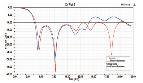
Figure 2. Simulated Bandwidth Comparison of Proposed Antenna without Slot and Classical Antenna
Further in the proposed antenna, all the ends of pentagon patch are truncated to improve the current distribution in the patch, which in turn improves radiation from the patch. Modifications are also performed on the partial ground plane of antenna. Two slots of quarter wavelength L = 5.25 mm and width W = 1.4 mm are cut from the s s ground which improves the gain of the antenna. In addition, a notch beneath the feedline is given on the ground with length L = 0.8 mm and width W = 2.58 mm st st which shows the improvement in return loss of the simulated result of antenna.
Performance analysis of proposed antenna is performed by varying the dimension of different parts of antenna, which are illustrated in the following Figures.
In Figure 3, the width of feedline is varied from 2.58 to 3.08 mm keeping rest of the dimensions constant as stated above.
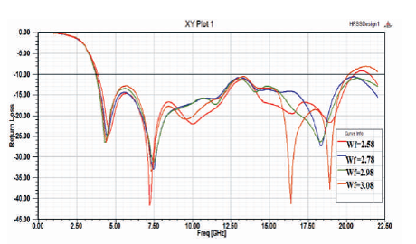
Figure 3. Return Loss Comparison of Proposed Antenna with Variation in Feedline Width (in mm)
As it can be observed from the graph (Figure 3), return loss begins to degrade specifically in 10-18 GHz when width of feed is increased from 2.58 mm, and resonant frequency also starts to shift at higher frequencies.
The variation of return loss with slot width is achieved, as observed from Figure 4, when the slot width is changed from 1.4 mm; return loss is reduced particularly at higher frequencies, thus 1.4 mm is the optimized slot width.
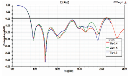
Figure 4. Return Loss Illustration of Proposed Antenna by Varying Width of the Slot(in mm)
In Figure 5, the variation of return loss with slot length can be seen from the which graph shows that, length is increased from quarter wavelength. The return loss almost reaches 10 dB near 12.5 GHz, and when length is reduced, frequency matching is not well at higher frequencies.
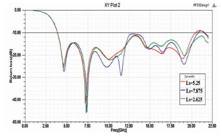
Figure 5. Return Loss Illustration of Proposed Antenna by Varying Length of the Slot (in mm)
In Figure 6, the results are also checked for variation in length of notch on ground plane, when the length is increased from 0.8 mm. Bandwidth is enhanced further but the return loss becomes very poor. Similarly, when the length is decreased, the peak return loss is reduced at resonance.
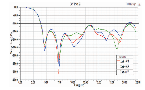
Figure 6. Return Loss Illustration of Proposed Antenna by Varying Length of the Notch (in mm)
As seen from Figure 7, the simulation of proposed antennas with and without slots in ground plane and truncation of pentagon patch at its edges, have almost same impedance bandwidth, where first antenna has somewhat large bandwidth, but remarkable difference in their reflection coefficient values. The antenna without slots and truncation has peak return loss of -37.65 dB at 7.3 GHz while the final proposed antenna has peak return loss of -43.07 dB at 7.7 GHz, which shows overall improved return loss values.
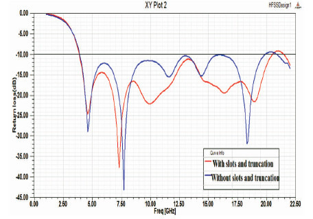
Figure 7. Return Loss Illustration of Proposed Antenna with and without Slots and Truncation at Ends of Pentagon Patch by Varying Length of the Notch (in mm)
In Figure 8, gain of both antennas are compared to each other, initially in the range of 3.85-6.25 GHz. The antenna without slots and truncation has more gain with peak gain of 4.96 dB. But as the frequency increases, at 6.25 GHz the final proposed antenna gain takes over and shows much improved gain performance, further due to the addition of slots and notches in the ground plane in the entire operating range with peak gain of 6.85 dB at 14.4 GHz. For such a compact size, antenna gain of this magnitude is admirable.
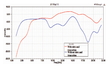
Figure 8. Gain (dB) Illustration of Proposed Antenna with and without Slots and Truncation at Ends of Pentagon Patch by Varying Length of the Notch (in mm)
The simulations for radiation pattern in E-plane and Hplane of antenna at different frequencies are performed and shown in Figure 9. The radiation pattern shows acceptable radiation in both planes with high strength of radiation; dips are observed at higher frequencies.
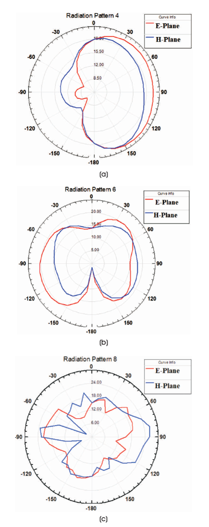
Figure 9. Radiation Pattern of Proposed Antenna in E-plane and H-plane at (a) 7.34 GHz, (b) 10.4 GHz, (c) 19 GHz
Current is observed in both pentagon patch and ground plane as shown in Figure 10. In patch, the current is maximum around the edges due to the truncation of edges and the circumference of the patch, which is almost equal to 2.5 times the wavelength of the patch. Similarly, the magnitude of current is maximum around the slots, as the slots have length equal to quarter wavelength in the ground plane.
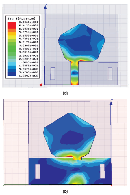
Figure 10. Current Distribution in (a) Patch and (b) Ground Plane at 7.4 GHz
The variation of real part of input impedance of the proposed antenna varies between 35.3 ohm and 80.28 ohm. Thus the impedance of the antenna does not deviates much from 50 ohm and matches well to the microstrip feedline, whereas the variation in imaginary part is observed from -12.3 ohm to 25.7 ohm, which reaches almost to the zero line near the resonance frequency of the antenna. The peak directivity of proposed antenna, obtained from simulated results is 0.30091.
The radiation efficiency of the proposed antenna is shown in Figure 11.
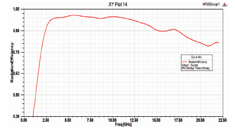
Figure 11. Radiation Efficiency of the Proposed Antenna
The performance improvement of a monopole microstrip antenna was proposed, and as it can be seen from the simulated results that the objective has been achieved. When the edges of the patch are truncated, slots are added in the ground plane and offset feed is given with modified dimensions. The proposed antenna shows impedance bandwidth of 16.65 (3.85-20.5) GHz, which is 60% enhanced bandwidth as compared to classical antenna, maximum gain of 6.85 dB at 14.35 GHz which shows 2.65 dB gain increment from classical antenna, peak return loss of -41.6 dB at 7.2 GHz. The strength of radiation pattern is also enhanced. All these improvements are made keeping the geometry of the antenna simple and easy for fabrication purpose. The application of this antenna lies in several bands such as UWB, X band and Ku band. The utilization of this antenna can be in the field of mobile communication for Worldwide Interoperability for Microwave Access (WiMax) band, Wireless Local Area Network (WLAN), Industrial, Scientific and Medical (ISM) band or in satellite communication for space research (13.24-15.4 GHz), for fixed and broadcast satellite services.