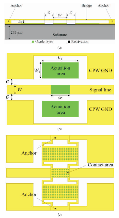
Figure 1. Proposed RF MEMS Capacitive Shunt Switch: (a) Top View and Contact Area (b) Top View without Bridge (c) Top View with Bridge
This paper proposes a design of zig-zag shaped Radio Frequency Micro Electro Mechanical System (RF MEMS) capacitive shunt switch with low spring constant and low activation voltage of the order of 4.7 V. In this design, there are two actuation electrodes and a separate signal line. Both electrodes and signal line are arranged such that, the whole arrangement isolates the Direct Current (DC) static charge and the input operating signal. The switch return-loss in upstate condition and the isolation in down-state condition were found more than 20 dB over a wide frequency band of 18 to 51 GHz.The switch yields insertion loss in up-state and return-loss in down-state condition, lower than 0.5 dB at same frequency band. The simulated results were verified through analytical method and are found to be in close agreement.
In the recent years, Radio Frequency Micro-Electro- Mechanical System (RF MEMS) switches have shown p o t e n t i a l p e r f o rma n c e i n mi n i a t u r e w i r e l e s s communication devices, such as mobile phones and satellite components (Petersen, 1979; Rebeiz, 2004; Rebeiz and Muldavin, 2001; Nguyen et al., 1998). The RF MEMS switches have replaced the conventional solid-state switches like, PIN diode, Gallium Arsenide (GaAs) and Field- Effect Transistor (FET) based switches, etc. The RF MEMS switches have significant advantages over conventional RF switches. These include very low insertion loss, higher isolation, lower cost, lower intermodulation distortion, nearly zero power consumption and more linear characteristics over a large range of frequencies (Fernández-Bolaños et al., 2008; Rebeiz et al., 2013; Kim et al., 2013). However, these advantages come with a challenge of maintaining low actuation voltage with high switching speed (Demirel et al., 2015; Angira and Rangra, 2015; Yao et al., 1999; Muldavin and Rebeiz, 2000).
Typically, the fabrication process of RF MEMS is based on the surface micromachining techniques. It has a suspended thin metal membrane called 'bridge' (cantilever and fixed-fixed beam), which uses mechanical movement to achieve open or short circuit in RF transmission line (Rebeiz, 2004). Therefore, they are normally integrated with Coplanar Waveguides (CPW). The RF MEMS switches can be classified mainly into two categories based on their actuation methods and circuit configurations. Actuation method is executed in different ways like, electrostatic (Lazaro et al., 2007), electromagnetic (Ruan et al., 2001), piezoelectric (Ke et al., 2009), thermal (Daneshmand, 2009), etc. Based on the circuit configuration, the RF MEMS switches can be classified as Ohmic Contact (Rebeiz and Muldavin, 2001) or Capacitive Contact (Kim et al., 2013). Out of the several actuation methods listed above, the electrostatic actuation is the most preferred actuation method due to low power consumption. In this method, an electrostatic force is produced between an actuation electrode and the bridge, for switching operation (Rebeiz, 2004; Rebeiz and Muldavin, 2001).
In this paper, a high-impedance CPW MEMS capacitive switch with low actuation (pull-in) voltage is proposed. Two pull-in electrodes with anchor support structure and vias in membrane help to lower the pull-in voltage of the proposed RF MEMS switch. The switch operates over a wide frequency range of 18 to 51GHz, satisfying the criteria of isolation, return-loss and minimum insertion loss.
The proposed RF MEMS switch, which includes a bridge, anchors and a 50 Ω rectangular CPW is shown in Figure 1. The bridge connects both the anchors. When electric force is applied between an actuation electron and a bridge, force is generated between them. The generated force pulls the bridge towards actuation electrodes. Silicon nitrate is chosen as a dielectric material to provide isolation between the bridge and a signal line. The pull-in electrodes and bridge dimensions are fixed such that the pull-in voltage is maintained to less than 5 V.
Figure 1. Proposed RF MEMS Capacitive Shunt Switch: (a) Top View and Contact Area (b) Top View without Bridge (c) Top View with Bridge
In the proposed RF MEMS switch, the activation DC voltage is not applied between the signal (center) line and the ground line. Instead, the actuation voltage is applied on two separate actuation electrodes. Because of this, no interference occurs between the actuation electrodes and the signal line conductors. Also, as reported by (Bhatasana et al., 2015), separation of RF signal and DC activation potential offers flexibility in practical modeling and analysis of a circuit.
The CPW line consists of a center conductor and two ground conductors as shown in Figure 1. The center conductor is used for signal transmission. When zero DC voltage is given to an actuation electrode, the bridge remains in up-condition and then the RF signal can transmit through the signal line. The DC voltage applied to the actuation electrodes can produce electrostatic force to attract the bridge in downward condition (Rebeiz, 2004). In this condition, the RF signal will be capacitive coupled between the bridge and signal line. All parameters used for designing RF MEMS shunt switch are listed in Table 1.
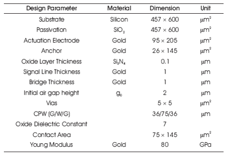
Table 1. Proposed RF MEMS Switch Design Parameters
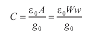
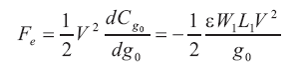
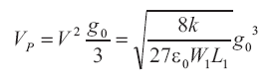
A parallel plate capacitance can be expressed as equation (1), where, g is the air beam height above the 0 electrode. The electric force is produced by applying electric potential and capacitance between the bridge and the signal line as given in equation (2). Variance in capacitance depends on air gap between the bridge and the signal line (Rebeiz, 2004). Under the applied electric field, the cantilever beam moves towards the signal line. In addition to this, spring constant must be associated with the distance moved under the amount of applied force. Beam movement is balanced by mechanical restoring force due to the stiffness of the beam. Beam becomes unstable when beam height becomes 2/3 of zero potential beam height (g ). So, 0 maximum pull down electric force (Activation Voltage) can be given up to the displacement of (2/3)g , as 0 mentioned in equation (3). Activation or pull-in voltage depends on spring constant (k), beam height (g ) and 0 width of signal line (W) as mentioned in equation (3).
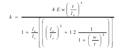
The spring constant of fixture as defined by Rebeiz (2004) can be written as,
By considering l >>l s c
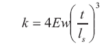
In expression (5), E is the Young's modulus of the bridge; t is the thickness of the bridge and l is the fixture length as s shown in Figure 2(a). As per equation (3), spring constant (k) plays an important role in deciding the activation voltage of a switch. The spring constant can be decreased by changing the mechanical structure of the bridge. Different methods are used to calculate the spring constant, which largely depends on the bridge structure. For the proposed switch, crag-lag type of fixture has been considered.
Two large zig-zag shaped suspension actuation electrodes are used on both sides to reduce the pull-in voltage. This is shown in Figure 2(a), (b) and (c). Due to the vias in a bridge, the overall switching speed increases. Also, at the same time, Young's modulus, mass of the bridge and the electrostatic force decreases (Rebeiz, 2004; Rebeiz and Muldavin, 2001). This action ultimately results in decrease of pull-in voltage to 4.7V.
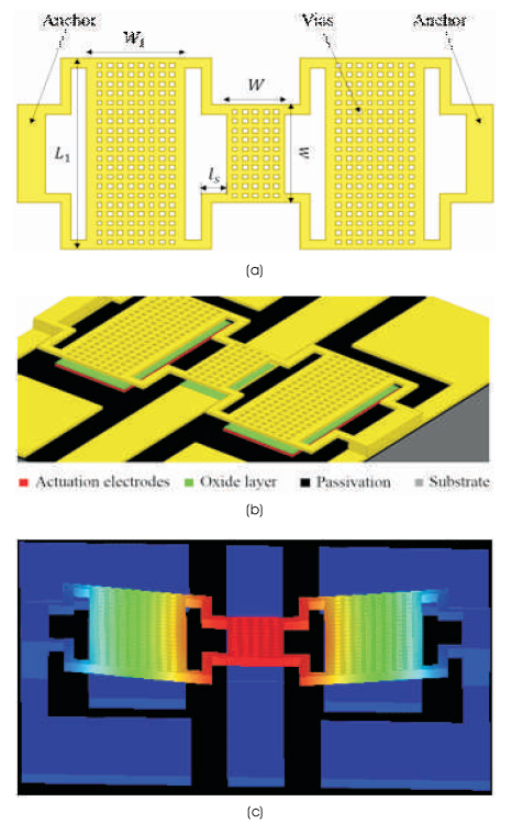
Figure 2. Proposed RF MEMS Capacitive Shunt Switch Bridge Structure: (a) RF MEMS Bridge Structure (b) Close-Up 3D View of the Bridge (c) Excited RF MEMS Switch
The electrical equivalent model of the proposed RF MEMS switch is shown in Figure 3. The impedance offered by the switch is given by equation (6).
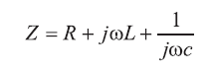
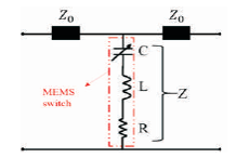
Figure 3. Electrical Model of the RF MEMS Switch
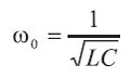
The resonant frequency of the switch can be given as,
In equation (7), C can be up-state capacitance (C ) or u down-state capacitance (C ), depending upon the d applied pull-in voltage to the bridge. Actual impedance offered by the switch for different applied frequencies is given by equation (8),
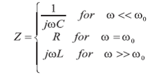
The Resistor, Inductor, Capacitor (RLC) model acts as a capacitive switch below the resonant frequency, and an inductive switch above the resonant frequency. At resonance, the RLC model acts as the series resistance of the MEMS bridge (Rebeiz, 2004).
As shown in Figure 4, by applying electric force to the actuation electrodes, the electrode is attracted to downward, depending upon the spring constant as given in equation (3). In the proposed design of the bridge, the spring constant decreases, which result into an air gap displacement of bridge by 66%, with an activation voltage of 4.7 V. This activation voltage can be compared with the close form formula as given in equation (5). The comparison of results is shown in Table 2.
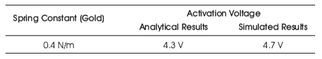
Table 2. Comparison of Analytical and Simulated Result of Activation Voltage
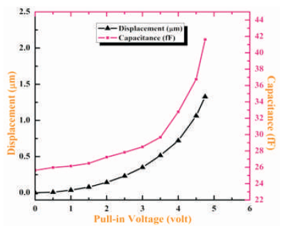
Figure 4. RF MEMS Pull-in Voltage vs Displacement and Capacitance
Up-state and down-state capacitance values are also compared with analytical method and the comparisons are shown in Table 3.
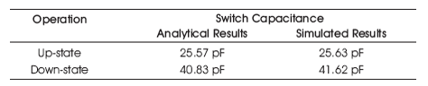
Table 3. Comparison of Analytical and Simulated Result of RF MEMS Shunt Switch Capacitance
Figure 4 shows that the air gap displacement of the bridge moving downward to 1 μm, which results into increase in signal line capacitance from 25.6 fF to 41.6 fF, where fF stands for femtofarad. From Figure 5, it can be concluded that by keeping the bridge width to 145 μm, the best performance of the switch can be obtained in the wide frequency range of 18 to 51GHz.
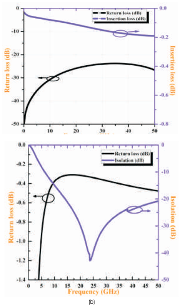
Figure 5. Signal Analysis RF MEMS Switch: (a) Signal Analysis of Up-state (b) Signal Analysis of Down-State
Reliable RF MEMS shunt capacitive coupled switch has been designed and optimized for RF and microwave applications. The required return-loss and insertion loss are obtained over a wide frequency range from18 to 51GHz. Low activation voltage of the order of 4.7 V is obtained by deployment of zig-zag shaped two separate actuation electrodes in the bridge.