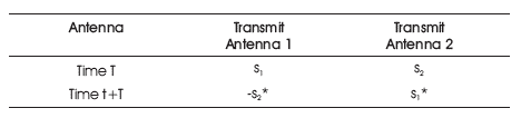
Table 1. Encoding and Transmission Arrangement of Alamouti's STBC
Due to the ever increasing requirement of faster data propagation, Multiple Input Multiple Output (MIMO) is an emerging topic in the future generation wireless communications in which spectrum efficiency, network coverage, and link reliability factors can be easily achieved. By combining MIMO and Phase Shift Keying (PSK) modulation, this paper proposes a novel technique termed as MIMO-PSK receiver in order to perform significant improvement in channel capacity in presence of Space-Time Block Coding (STBC) over multipath fading channels. STBC provides full or near full data rate according to its orthogonality principle. Higher order MIMO-PSK receiver configurations are mainly considered for simulating optimal channel performances, i.e. Bit Error Rate (BER) as well channel capacity. From MATLAB simulations, it is clear that optimal channel performance of MIMO-PSK receiver can be obtained with increasing number of antennas as well as higher order PSK modulation.
Future generation wireless communication is mainly concentrated on high transmission speed over multi scattering environments. The basic principle of MIMO wireless communications is represented in [10] that offers future Gigabit data speed over Single Input Single Output (SISO) according to its design and coding paradigm. Multi antenna techniques in combination with space time block coding, i.e. MIMO-STBC provides significant raise in transmission rate as well as channel capacity by encoding multiple data blocks in different spatial domains and attains full or near full data rate by using transceiver diversity. Alamouti first introduced a novel transmit-receive diversity technique using 2×1 antenna configuration that achieves the same diversity order for Maximal-Ratio Receiver Combining (MRRC) with 1×2 transceiver antennas [1]. Consequently, this technique can further be implied to 2×M transceiver antennas to gain a diversity order of 2M without adding any further drawbacks in terms of bandwidth and computation complexity. Based on channel state information, a unique state of the Alamouti's STBC system with a diagonal weighting matrix in terms of a feedback link is presented in [6]. Code design as well as performance criterion of STBC is studied in [14, 15] using its orthogonality principle. STBC as well as Spatial Modulation (SM) cooperatively known as (STBC-SM), expands the transmitted symbols in spacetime and antenna domain [2, 18] in order to exhibit enhanced channel performance compared to simple SM and V-BLAST. In [7], the BER performances on receiver selection combining over Rayleigh fading are analyzed for Alamouti STBC with BPSK. With Single-Carrier (SC), STBC transmission scheme is studied over frequency-selective multipath fading channels [19] [4] while [13] proposes a new STBC transmit antenna selection scheme for two or more transmit antenna over spatially correlated fading channels. Multiple user detections of Alamouti signals over multipath environments have been carried out in [12]. Using Unique Word (UW) technique, [16] introduces a new Distributed Space-Time Block Codes (D-STBCs) termed as D-UW-STBC in order to minimize the effect of additive noise for dual hop wireless relay phenomena. A new design criterion of Multiple Access Channels (MACs) MIMO for multiuser STBCs with quasi-static fading and reduced Union-Bound (UB) approximation is proposed in [5]. The exact BER for the combined beam-forming and Alamouti STBC with 2×1 antennas over slow Rayleigh flat fading channels is analyzed in [8]. The design paradigm as well as performance comparison of Alamouti STBC over multipath fading channels for different transmitreceive antennas is carried out in [9], [11]. The BER performance of Distributed Space Time Block Coded (DSTBC) system over cooperative time-varying as well as frequency-selective fading channels is studied in [3], [17] for two-hop amplify and forward relay networks. To the extent, growing demand of future generation wireless communication requires greater amount of data transmission over multipath fading environments with long distances, hence it is crucial to achieve higher signal strength with minimum BER at the receiving antenna. Therefore, this paper focuses on the most favorable channel performance in terms of optimal performance at MIMO-PSK receiver by attaining minimum BER under variable transmit-receive antenna combinations when PSK modulation is employed. Although other space-time coding methods exist, in the present research, principle of Alamouti STBC with variable antenna and PSK configurations is chosen mainly for its simplicity and greater performance.
In 1998, Alamouti was the first who introduced a coding scheme in order to achieve full transmit diversity for 2×1 antenna configuration in presence of no channel state information. Figure 1 depicts the MIMO Alamouti space time encoder block diagram in which data is first transmitted from the source and then encoded according to PSK modulation. In the transmitter side, two symbols s1 , s2 are taken as a block and they are modulated and encoded in time and spatial domain. That is why it is called space-time block codes, i.e. Alamouti STBC. The code matrix of Alamouti's STBC model can be presented in a tabular form as in Table 1.
Table 1. Encoding and Transmission Arrangement of Alamouti's STBC
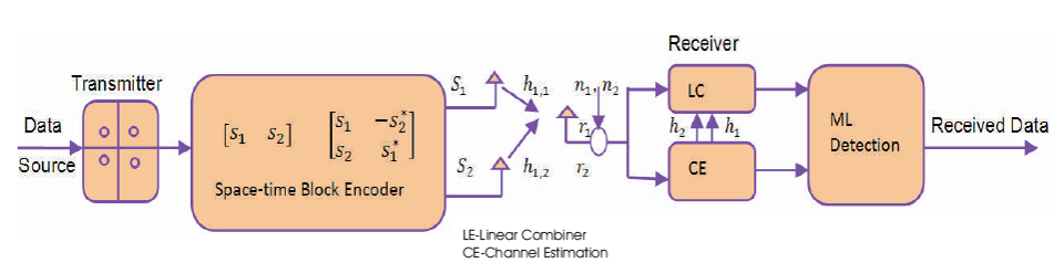
Figure 1. Alamouti Space Time Encoder Block Diagram
The coded symbols are then transmitted through two transmit antenna according to the following code matrix,

where, rows 1 and 2 represent the transmission data from antenna 1 and 2, respectively and columns 1 and 2 represent transmission data at period 1 and 2, respectively. * indicates complex conjugate of transmission symbols. From Table 1, these two relations can be obtained:


Thus,
This shows that the sequences are orthogonal. At time t and t+T, the received signals r1 and r2 can be expressed as,


where, n1 and n2 represent the additive white Gaussian noise at time t and t+T, respectively. Assuming the complex conjugate of the second received signal, the matrix vector equation obtained can be given as follows:

Therefore, from time t to t+T, the channel estimator estimates h and h for the channels. In an ideal situation, the channel gains, h1 and h2 , are exactly known to the 1 2 receiver. But in equation (7), these both are unknown variables. Multiplying both sides of equation (7) by the Hermitian transpose of the channel matrix, the matrix vector of received signal can be expressed as,

So, the transmit-receive matrix vector relation can be obtained as follows,

In this equation, unwanted signals s2 and s1 are subtracted from r1 and r2 , respectively. This eliminates the antenna interference from the system which is the principle of complex orthogonality of the Alamouti code expressed in equation (1). This specific feature allows for simplification of the ML receiver structure as follows:

Here, Q() indicates a slicing function that determines a transmit symbol for the given constellation points. The above equation implies that s1 and s2 can be evaluated separately. As a result, the decoding complexity of original ML-decoding algorithm reduces from |G|2 to 2C where C stands for the constellation of the modulation symbols, s1 and s2 . In addition, the scaling factor (|h1|2+|h2|2) in equation (6) ensures the second-order spatial diversity that is the salient feature of the Alamouti code.
In MIMO systems, Alamouti scheme has opened an era by achieving full transmit diversity without any prior channel state knowledge and gives very simple maximum likelihood detection at the receiver. Figure 2 describes the block diagram of the space-time block encoder for 2×2 antenna combinations. ML detection provides full diversity gain of Nr at the receiver. Hence, such a systemprovides a certain overall diversity gain of 2N , which is r achieved due to the orthogonality of two transmit antennas. This scheme can be extended to a more generalized model with an arbitrary number of transmitreceive antennas which is known as Space-Time Block Coding (STBC). STBC can achieve the full transmit diversity of NtNr by ML detection according to linear processing of received signals whereas N and p represents the number t of transmit antennas and time periods for transmission of one block coded symbols, respectively. The signal constellation can be considered as 2m points. Then each encoding operation maps a block of km information bits into the signal constellation to select t modulated signals s1, s2 ,.....st, where each group of m bits selects a constellation signal. These t modulated signals are then encoded in a STBC to generate Nt parallel signal sequences of length p with a transmission matrix S of size Nt x p. These sequences are transmitted through Nt transmit antennas simultaneously in p time periods. Therefore, the number of symbols the encoder takes as its input in each encoding operation is t. The number of transmission periods required to transmit the entire S matrix is p. The rate of the STBC is defined as the ratio between the number of symbols the encoder takes as its input and the number of space-time coded symbols transmitted from each antenna. It is given by,

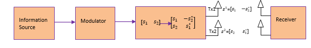
Figure 2. Block diagram of the Space-Time Block Encoder for 2×2 Antenna
The entries of the transmission matrix S are so chosen that they are linear combinations of the t modulated symbols s1, s2,.....st and their conjugates s*1, s*2,.....*st. The matrix itself is so constructed based on orthogonal designs such that,

where k is a constant, Nt is the number of transmit antennas, SH is the Hermitian of S, and INT is an identity Nt × Nt matrix. This approach yields a diversity of Nt. These code transmission matrices are cleverly constructed such that the rows and columns of each matrix are orthogonal to each other. If this condition is satisfied, the full transmit diversity of Nt is achieved.
Depending on the constellation STBC can be classified as real signals or complex signals. Here, the authors consider the case for real antennas. It gives square transmission matrices when number of transmission matrices are N =2, t 4, 8. These matrices are square matrices, i.e. 2×2, 4×4, and 8×8, as a result gives full transmit diversity of N . The t transmission matrix for Nt=2 is given by,

When Nt=4 it is expressed as,

In case of Nt=8 it is expressed as,

Non-square matrices of size 3, 5, 6, and 7 for real number of antennas can also be constructed that yields full diversity and full rate. These are as follows:


The transmission matrix S7 is taken as a comparison. In this example, k = 8, as there are eight symbols involved, s1, s2,.....s8, with eight transmission periods, p = 8. These eight symbols over eight transmission periods are transmitted from seven antennas as before. This yields the full diversity of Nt=8 and a code rate of

The STBC can be applied for different number of receiver antennas. For four transmit antennas, the real STBC, s 4,real can be expressed as: The entries of the transmission matrix S are so chosen

From which, following relationship can be obtained

According to the orthogonality principle of STBC,

Using the above result, the ML signal detection is performed as,

Phase Shift Keying is widely used in wireless communication that uses multiple phases according to the phase displacement. PSK modulations use m different phases depending on angular separation. As a common example of PSK, Figure 3 shows the constellation diagram of a QPSK that uses quadrature phase positions which are equi-distant to each other on a circle.
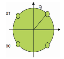
Figure 3. QPSK Constellation Diagram
For QPSK, two bits per symbol are to be encoded. In a BPSK, there are two states while QPSK has four states, so QPSK has double bandwidth than that of BPSK. For generalized PSK modulation of any order, the number of phases can be varied depending on the states used in the modulation. As different phases are placed equi-spaced around a circle, PSK modulation is used to implement for achieving the optimal channel capacity.
The simulations studies are carried out using MATLAB toolbox. The BER performances of MIMO-PSK receiver have been evaluated as a function of SNR for M-ary PSK modulation for different Alamouti STBC antenna configurations. The parameters those are used for simulation purposes and the evaluated BER versus SNR performance are given in Table 2.
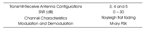
Table 2. Simulation Parameters of Variable MIMO-PSK Receiver with STBC
Figures 4, 5, and 6 represent the MIMO-PSK BER performance comparisons of STBC with 3×3, 4×4, and 5×5 MIMO-PSK receivers when different orders of PSK modulations are applied. From Figures 4, 5, and 6, it is seen that the performance of Alamouti STBC increases gradually with higher orders of PSK modulation than the lower orders irrespective of transmit antenna conditions, i.e. for 3, 4, 5 transmit antennas, the BER is lowest for 32-PSK and highest for BPSK. The minimum attainable BR, i.e. optimal BER is indicated in Table 3.
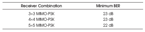
Table 3. Achievable Optimal BER for Variable MIMO-PSK Antennas
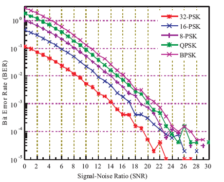
Figure 4. BER Performance Comparison of 3×3 MIMO-PSK Receivers with STBC
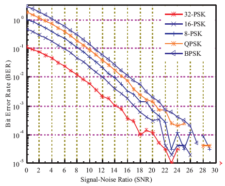
Figure 5. BER Performance Comparison of 4×4 MIMO-PSK Receivers with STBC
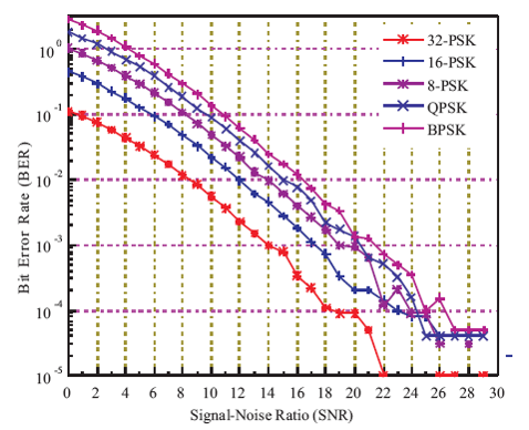
Figure 6. BER Performance Comparison of 5×5 MIMO-PSK Receivers with STBC
Next, the MIMO-STBC signals are simulated by changing the transmit-receive antennas while keeping PSK modulation same. For 3, 4, and 5 transmit antenna configurations, the receiver antennas are varied and resultant characteristics of MIMO-PSK receiver for STBC is presented by Figures 7, 8, and 9, respectively.
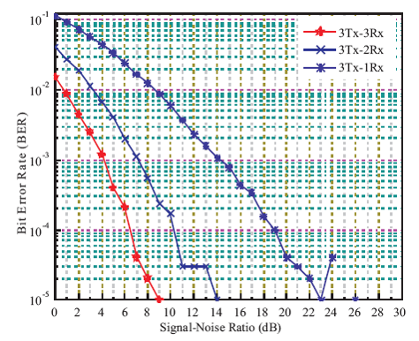
Figure 7. BER Performance of MIMO-PSK Receivers with STBC and 5-Transmit Antennas
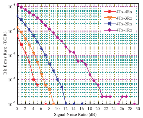
Figure 8. BER Performance of MIMO-PSK Receivers with STBC and 4-Transmit Antennas
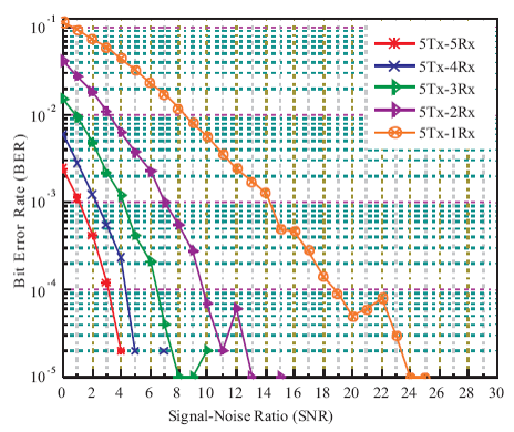
Figure 9. BER Performance of MIMO-PSK Receivers with STBC and 5-Transmit Antennas
From the Figures 7, 8, and 9, it is seen that the BER performance are continuously improved for higher transmit antennas, i.e. for five transmit-five receive antennas, BER is minimum than four transmit-four receive and three transmit-three receive antenna cases that is indicated in Table 4. The performances are analyzed for 3, 4, and 5 MIMO-PSK receiver in terms of variable PSK modulation under multipath fading environments. These results clearly express that the higher the transmit antennas, the better the BER performance at the MIMOPSK receiver. Combining all of the simulation results, it is obvious that 5×5 MIMO-PSK receiver and 32-PSK exhibit minimum BER.
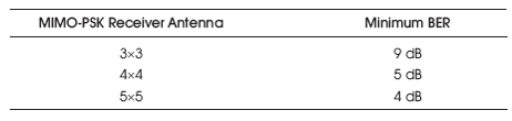
Table 4. BER Relation of Variable MIMO-PSK Antenna with STBC
In this paper, MIMO-PSK receiver performance with Alamouti STBC over multipath fading phenomena at variable PSK modulation and different antenna configurations are presented. This simulations exhibits significant channel per formance than that of conventional MIMO receiver. The simulation results show that for higher order PSK modulation and higher number of transmit-receive antennas, MIMO-PSK receiver with STBC exhibits optimal BER. However, further research on MIMOPSK with different space time coding methods can be implied in order to improve the channel performance more.