 Performance and Analysis of PWM Inverter Fed 3-Phase PMSM Drive
In this work, the performance of three phase PWM inverter fed PMSM drive is analyzed on the latest Matlab Simulink environment. Efforts have been made to reduce the distortion and harmonic contents in the current waveform. This has been done by varying parameters of the motor along with suitable variation in the parameters of PI controller. The motor was subjected to a step load. It has also been found that, by providing power supply in discrete form improved the current waveform and also reduced ripples in the torque. This observation paved way to sample the load at the same rate as of that of power supply. The authors have also calculated the Total Harmonic Distortion (THD) in the current waveform by Fast Fourier Transform and finally observed that due to different level of transient in each phase there is a variance in THD.
In the recent past, the use of Permanent Magnet Synchronous Motors (PMSMs) has increased considerably owing to their inherent advantages. The high performance speed and/or position control of a PMS motor requires an accurate knowledge of rotor shaft position and angular speed in order to synchronize the phase excitation pulses to the rotor position [1, 6].
Permanent Magnet (PM) synchronous motors are widely used in low and mid power applications, such as computer peripheral equipments, robotics, adjustable speed drives, and electric vehicles [8].
The growth in the market of PM motor drives has demanded the need of simulation tools capable of handling motor drive simulations. Simulations have helped the process of developing new systems including motor drives, by reducing cost and time. Simulation tools have the capabilities of performing dynamic simulations of motor drives in a visual environment so as to facilitate the development of new systems [5, 9].
In this work, the simulation of PMSM closed loop control system with a PI controller in the speed loop has been designed to operate in constant torque implementation. This work has been done in the recent Matlab/Simulink environment.
In previous literatures, ideal components have been assumed in the inverter feeding the motor and simulations have been done. The voltages and currents in different parts of the inverter have not been obtained and hence the losses and efficiency cannot be calculated. In this work, the simulation of a PM motor drive system is developed using Matlab Simulink. The simulation circuit includes all realistic components of the drive system. A comparative study associated with hysteresis and Pulse Width Modulated (PWM) control techniques in current controllers has been made. A speed controller has also been designed for closed loop operation of the drive.
T. A. Lipo in 1980 derived a d-q model for a six phase induction machine. In particular, the slot leakage coupling between three phase groups is incorporated into the model, when the equations are specialized to sinusoidal steady state, it is shown that the usual per phase equivalent circuit results [4].
Ho-Yong Choi, Sun Jung Park, Young Kyung Kong, and Jae Goo Bin in 2009 gave a design proposal of permanent magnet Synchronous motor for ship propulsion. The appropriate number of poles and slots are selected and the cogging torque is minimized in order to reduce noise and vibrations [2].
Mingzhong Qiao, Xiaofeng Zhang, and Xiuming Ren in 2002 presented the mathematical models of p-pair poles N-phase sine wave permanent static reference frame and d-q rotating reference frame were established. The maximum transient short-circuit current of the motor was deducted. Experiment showed that the mathematical models established and short circuit current expressions deducted were correct [7].
Iyer and Jiangsu Zhu in 2005 described, modeling of a six step discontinuous current mode inverter fed PMSM drive using simulink. The block diagram of six step inverter fed PMSM drive is as shown in Figure 1. The d-q-axis voltagecurrent and torque relation in terms of machine parameters were developed using the simulink model. A six step 120 degree mode inverter model was developed by using Simulink [3].
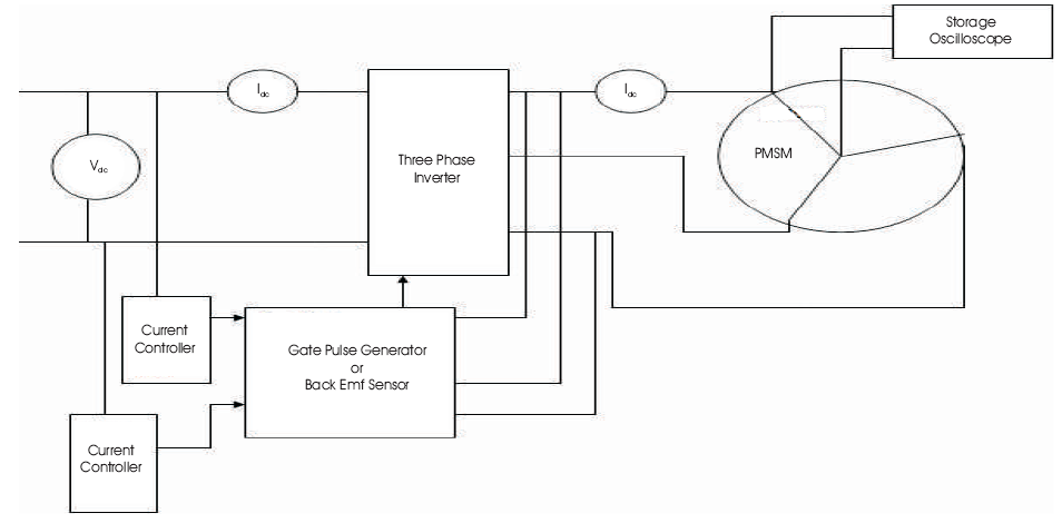
Figure 1. Block Diagram of Six Step Inverter Fed PMSM Drive
It has been observed that the three phase supply is not purely sinusoidal in nature. Almost, all loads are non-linear in nature. These non linear loads lead to the harmonics that cause a lot of problems to the loads like heating effect, ripples in torque, and non smooth current. The authors have studied Journal papers and collected distributed data. They have done analyzes of these primitive issues and tried for rectification. They have done modelling of 3 phase inverter fed PMSM drive and then simulated in the latest MATLAB/Simulink environment. By varying the values of motor and PI controller parameters, the main aim of this work is reduction of total harmonic distortion and ripple free torque.
This section deals with the detailed mathematical modeling along of a permanent magnet synchronous motor. The mathematical model is drawn on the basis of Park's Transformation theory of resolving a 3 phase into 2 phase d-q model. Closed loop control of the motor is developed using a PI controller in the speed loop.
The detailed modeling of PM motor drive system is required for proper simulation of the system. The d-q model has been developed on rotor reference frame is as shown in Figure 2. At any time t, the rotating rotor d-axis makes an angle θ with the fixed stator phase axis and r rotating stator MMF makes an angle α with the rotor d-axis. Stator MMF rotates at the same speed as that of the rotor.
The model of PMSM without damper winding has been developed on rotor reference frame by considering following assumptions,
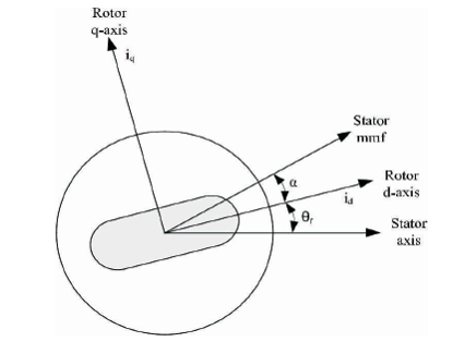
Figure 2. Motor Axis
The q and d-axis voltage equations are given in (1) and (2)


where,


Substituting equations (3) and (4) into (1) and (2),


Arranging equations (5) and (6) in the matrix form,

The developed electromagnetic torque in the motor is given by equation (8),

The mechanical torque equation is given by the following equation,

Equation (10) is solved for rotor mechanical speed,


The dynamic d-q modeling is used for the study of motor during transient and steady state. It is done by converting the three phase voltages and currents to d-q variables by using Park's Transformation.
On conversion of the phase voltages variables V to V abc dq0 variables in rotor reference frame, the following equations are obtained,

On converting the voltage variables V to V the dqo abc following equation is obtained,

Equivalent circuit of the motor has been used for study and simulation of the motor. From the d-q modeling of the motor using the stator voltage equations, the equivalent circuit of the motor is as shown in Figure 3. Assuming rotor d axis flux from the permanent magnets is represented by a constant current source as described in the following equation λ = L obtained.
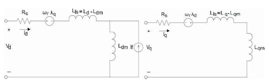
Figure 3. Permanent Magnet Motor Electric Circuit without Damper Windings
The block diagram of the inverter fed PMSM drive is as shown in Figure 4. The motor drive consists of four main components, the PM motor, inverter, control unit, and the position sensor. The position sensor detects the rotor position and senses the rotational changes and transform it into its angular velocity. This information is send to the controller which now has the information of the rotor position. According to the value of speed the controller sends signal to the pulse generator.
The block diagram shown in Figure 4 has been converted into simulation model and is shown in Figure 5. The simulation has been done in the latest MATLAB simulink environment. The rotor position is sensed through position sensor which converts this change in position into its angular velocity and thus is send to the comparator where it is compared with the reference speed of 1200 rpm.
The difference signal from the comparator is send to the PI controller, from where the signal is send to the converter circuit. In the converter circuit, we set the value of I as 0 and convert the 2 phase components into refrence 3 phase current. The refrence three phase current is reqiured to produce pulses which is fed to the PWM inverter. The inverter generates 3 phase voltage which is fed to PMSM.
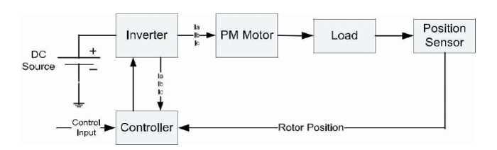
Figure 4. Block Diagram of PMSM Drive
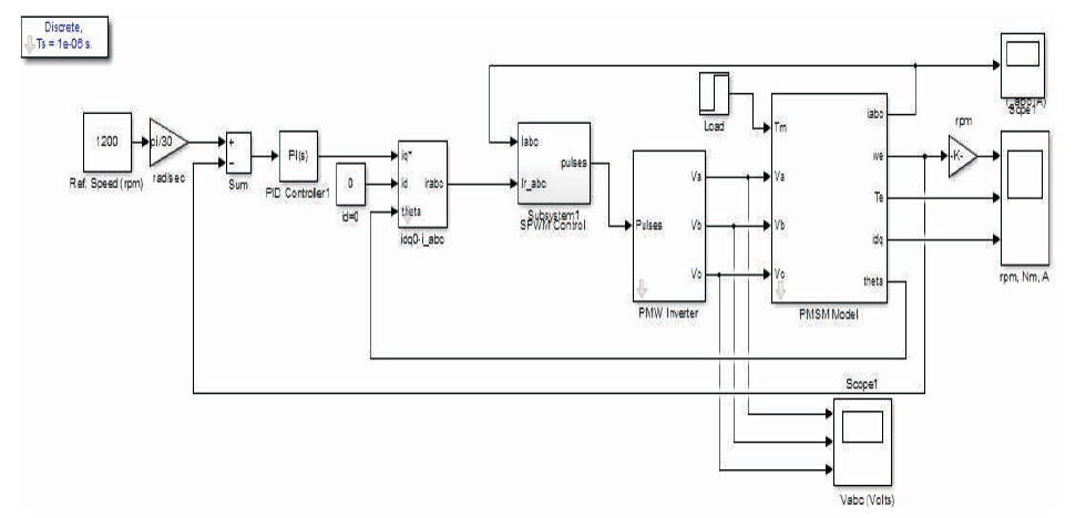
Figure 5. Simulation Model of Three Phase PMSM Drive
Pulse Width Modulation or PWM technology is used in inverters to give a steady output voltage of 230 or 110 V AC irrespective of the load. The inverters based on the PWM technology are more superior to the conventional inverters. The use of MOSFETs in output stage and the PWM technology makes these inverters ideal for all types of loads.
In addition to the pulse width modulation, the PWM Inverters have additional circuits for protection.
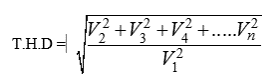
The quality of the output waveform (230 / 110 volt AC) from the inverter determines its efficiency. The quality of the inverter output waveform is expressed using Fourier analysis data to calculate the Total Harmonic Distortion (THD). The THD is the square root of the sum of the squares of the harmonic voltage divided by the fundamental voltage.
Based on the output waveforms, there are three types of Inverters. These are Sine wave, Modified Sine wave or Quasi sine wave, and Square wave inverters. The complete PWM inverter block diagram is as shown in Figure 6 for complete understanding purpose.
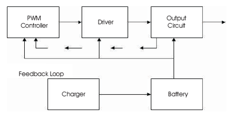
Figure 6. PWM Inverter Block Diagram
This section describes the results obtained on simulating the three phase PMSM drive in discrete power supply with a step load. The performance and analysis of the PMSM motor has been done by varying several motor parameters, such as motor current, rotor resistances, etc. In the past, it has been seen that the Motor Current Signature Analysis (MCSA) technique widely used in many power electronics and drives applications. Therefore, in this work, an analysis is done on motor current along with other motor parameters in time domain.
Figure 7 shows the 3 phase currents I , I , I , which is a b c displaced by 120 degrees. Initially it contains transients this is due to inrush current in the motor due to empty magnetizing branch so as to setup flux. The level of transient is different and adds up to 0 at any point. The transient remains up to half cycle to 2 cycles. To remove transient or to get better result, we could go for more number of phases.
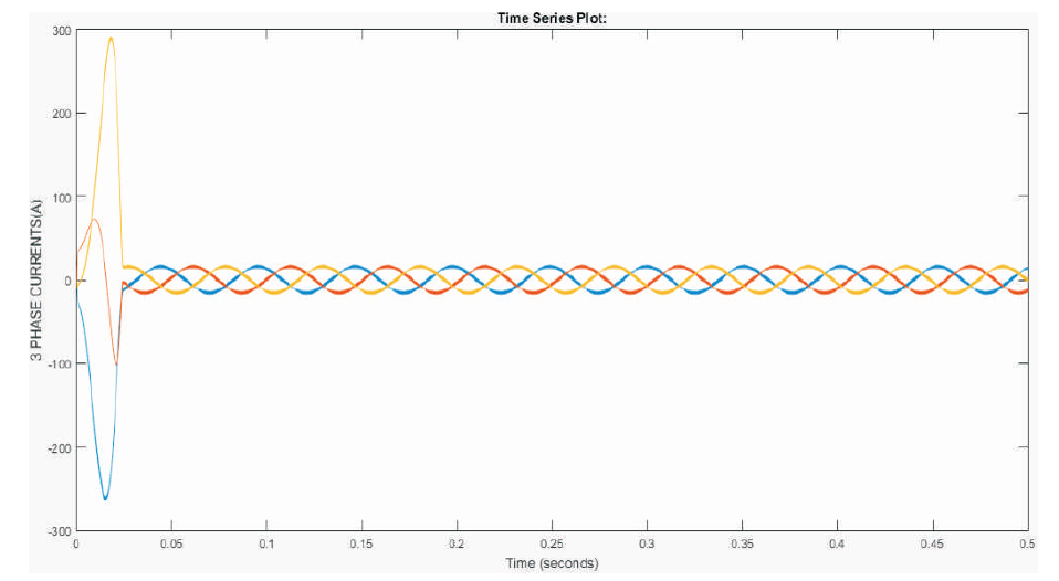
Figure 7. Three Phase Currents of the PMSM Motor
Figure 8 represents changes in direct and quadrature axis currents I and I . Since, I value is considered as 0, it starts d q d with 0 and then acquires the value according to Park's theory. Due to varying reluctance, the value of current drawn has been varied hence the direct and quadrature axis currents will be different. Since the reactance of direct axis is greater than the reactance of q-axis (X > X ) d q consequently I
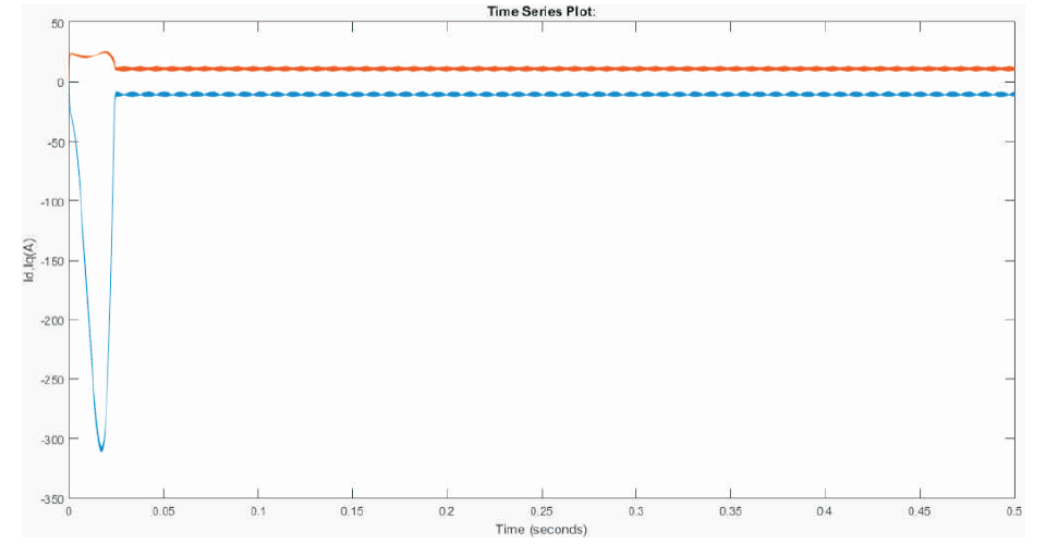
Figure 8. Plot of I and I Currents obtained after Conversion of 3 Phase to 2 Phase
Figure 9 shows the variation of torque produced with time since the step load is sampled and is not continuous. Since, the load torque fluctuates, this variation of torque is due to the harmonics produced by the PWM inverter. In order to reduce the ripples, there is a need to reduce harmonics.

Figure 9. Variation of Electro Magnetic Torque generated within the Machine
The ripples produced in the torque would lead to jerk, so in order to remove the effect of jerk, we need to increase the inertia level or attach a flywheel so that we have increased the inertia.
Figure 10 shows the variation in speed of the PMSM with discrete step load. This shows that the motor is working at a speed of 1195-1198 rpm. This proves the excellent speed regulation of the motor. This variation is sensed by the position sensor and is send to the comparator block for further analysis and working. This speed change could also be removed by increasing the inertia level.
h3>4.1 Techniques acquired to improve the ResultIn many research papers, it is found that the result obtained in simulating the PMSM drive contain a lot of harmonics in current waveform and ripples in the torque. The distortion level is observed very high due to transients.
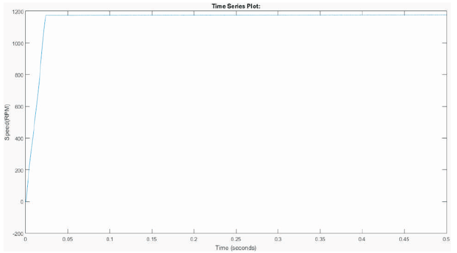
Figure 10. Variation in Speed with Time
To improve the transient behavior some authors used ANN controller.
In this work, the authors have analyzed the circuit and by selecting the proper techniques and methods the distortion level reduced to a greater extent. The parameters of the PI controller has been selected on Hit and Trial basis and the parameters of the machine selected on the assumption that the PMSM used is a medium or a high power rated machine such that the stator resistance is very low and the machine rotor is of high inertia.
Along with all this, the power supply is not continuous, but is -6 discrete with a sampling rate of 1×10 . At last, the step load has also been sampled at the same frequency to maintain proper synchronization between supply and load.
The Fast Fourier Transform of any signal may be carried out in order to calculate the Total Harmonic Distortion (THD). The FFT window of the motor current in phase a is shown in Figure 11. The fundamental frequency of the supply is chosen to be of 60 Hz while the maximum frequency is chosen to be 1000 Hz. The number of cycles chosen is 10 to minimize the effect of transients. The THD obtained will be different for different phases. Here, only phase a is considered. The THD calculated is 16.35%. The results obtained are quite satisfactory and consequently could be used for further analysis.
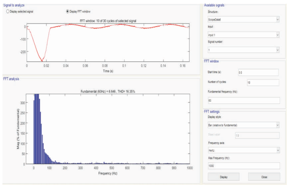
Figure 11. FFT Window showing THD
A detailed simulation model for a PMSM drive system has been developed and operated at a speed analyzed. The inverter fed PMSM simulation model has been made by using several simulation tools because of its flexibility in working with analog and digital devices. The mathematical model has been incorporated in the simulation and the presence of numerous tool boxes and support guides simplify the simulation of large system compared to P-Spice. The MATLAB simulation is capable of showing real time results with reduced simulation time and debugging for this application.
From this proposed simulation model, it has been shown that the output waveform of three phase current contain transients as well as harmonics, this is due to the usage of PWM inverter along with a non-linear load. The THD obtained is different for currents in different phases due to the fact of different level of transient in different phases.
In this work, the authors have tried for minimzing harmonics in the current as well as in other parameters of the motor. But, waveforms still have harmonics due to the presence of inverter in the model. Therefore, in order to eliminate transients, the need of multi-phase drives has been recommended. The Multi-Phase drive contains some inherent advantages which are as follows,
In future, Multi-Phase PMSM drives could be taken and enacted upon by,