Figure 1. Basic Switched DC-DC Converter
This paper presents a new topology of Bidirectional Buck Boost Converter which produces a regulated DC output. This converter provides the steady state output using both buck and boost operation and produces an output voltage which is maintained constant with either higher or lower input voltage. The average output voltage of buck-boost converter depends upon duty cycle (D), frequency (f) and input voltage (Vs). The switching frequency is maintained at 1 kHz and the output is maintained constant at 230V DC. The main application of this project is in the working of hybrid electric vehicle. By implementing this circuit in the architecture of the hybrid electric vehicle the efficiency of operation of the vehicle is increased and the cost involved is reduced. The entire proposed circuit is designed and simulated by MATLAB\SIMULINK and verified with hardware results.
The main purpose of a DC-DC converter is to supply a regulated DC output voltage to a variable-load resistance from an unstable DC input voltage. DC-DC converters are commonly used in applications requiring regulated DC power, such as computers, medical instrumentation and communication devices. DC-DC converters are also used to provide a stable variable DC voltage for DC motor speed control applications. There are three types of DC-DC converters in use today, linear converters, switched capacitor converters (also known as charge pumps), and switched converters. Linear converters can only generate lower output voltage from the higher input voltage. Their conversion efficiency is never greater than Vout /Vin . In practice, most linear out in converters operate with typical conversion efficiencies of only 30%. This is the major limitation which makes linear converters not suitable for the task of this paper. However they are commonly used in analog circuits to ensure a constant (or nearly constant) power supply voltage.
Switched capacitor converters implement switches and capacitors to perform voltage conversion. Since they do not use magnetic components like inductors the amount of EMI (Electro Magnetic Interference) is low which makes these converters suitable for applications which are sensitive to this phenomenon. Switched converters operate by passing energy in discrete packets over a switch. Hence, the output voltage can be higher, lower or inverted compared to the input voltage. They offer higher power efficiency than their linear and switched capacitor counterparts. However, switched converters generate significant amounts of electrical noise caused by the switching activity[1].
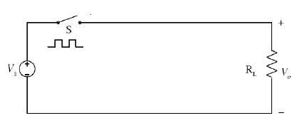
The output voltage in switched DC-DC converters is generally controlled using a switching technique, as illustrated by the basic switched DC-DC converter shown in Figure 1.
Figure 1. Basic Switched DC-DC Converter
There are three main topologies of switched DC-DC converters used today:
The most widely used method for controlling the output voltage through the switch is pulse-width modulation (PWM). The pulse-width modulation control technique maintains a constant switching frequency and varies the ratio of the charge cycle (time when the switch is on) and the discharge cycle (time when the switch is off) as the load varies. This technique affords high power efficiency. In addition, because the switching frequency is fixed, the noise spectrum is relatively narrow, allowing simple lowpass filter techniques to greatly reduce the peak-to-peak voltage ripple at the output. This is a reason why, PWM is popular in telecommunication applications where noise interference is of concern [2].
Certain applications require voltage levels to be both higher and lower than the source voltage. A solution to this is a buck-boost converter. A simple buck-boost converter is shown in Figure 2. The basic operation of a buck-boost converter is as follows.
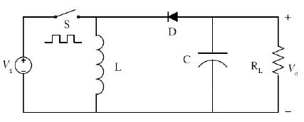
Figure 2. Buck-Boost Topology
When the switch is closed energy from the source is transferred to the inductor and the diode is reversedbiased, thus, it is off. This mode of diagram is shown in Figure 3.
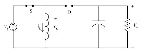
Figure 3. Mode 1 Operation of Buck-boost Converter
The switch is open and the inductor maintains the current direction. This forward-biases the diode. During this period the inductor is transferring energy to the capacitor. In other words, the capacitor is being charged as the inductor is being discharged, and the output voltage is rising. This Mode of diagram is shown in the Figure 4.
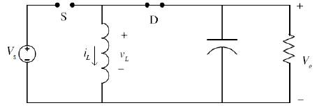
Figure 4. Mode 2 Operation of Buck-boost Converter
Previous discussion implies, that by adjusting the on time of the switch compared to the time of one switching period, the output voltage Vo can be set to either lower or higher levels than the input voltage Vs . If the ratio of the on time of the switch and the switching period approaches zero than the output voltage also approaches zero. If the ratio approaches one, than the output voltage level theoretically has no upper limit.
Next step is to select a suitable control scheme for circuit considering the high power efficiency requirements. Three control scheme approaches will be analyzed and described in the following sections.
By adjusting the Ton / Toff ratio the average output voltage can be controlled. A popular solution for generation of switch control signal is to compare Vcontrol with a repetitive waveform.
Ts =Ton +Toff
Where,
Ts is constant time switching period
Ton is the switch is on time
Toff is the switch is off time
Vcontrol is obtained by amplifying the difference between the actual output voltage from the converter and its desired value. The frequency of the repetitive waveform, represented by the saw tooth voltage in Figure 5 establishes the switching frequency. This frequency is kept constant in a PWM control. When the amplified error signal, which varies slowly with time relative to the switching frequency, is greater than the saw tooth waveform, the switch control signal becomes high, causing the switch to turn on. Otherwise, the switch is off. In terms of vcontrol and the maximum value of the saw tooth waveform in Figure 6 the main advantage is the use of single switching frequency which makes the level of output ripple highly controllable.
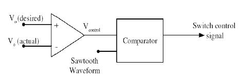
Figure 5. PWM System Block Diagram
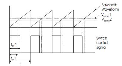
Figure 6. PWM Control Signals
One control scheme which obtains high power efficiency over a wide range of loads is pulse-frequency modulation (PFM). In this scheme, the converter is operated only in short bursts at small load as is conceptually illustrated in Figure 7.
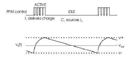
Figure 7. Pulse-Frequency Modulation
A hybrid vehicle is a vehicle that uses an on-board rechargeable energy storage system (RESS) and a fuel based power source for vehicle propulsion. These vehicles use much less fuel than their counterparts and produce less emission. Hybrid vehicles recharge their batteries by capturing kinetic energy through regenerative braking. Some hybrids use the combustion engine to generate electricity by spinning a generator to either recharge the battery or directly feed power to an electric motor that drives the vehicle. This takes place when cruising or in other situations where just light thrust is needed [3]
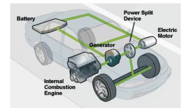
Figure 8. Hybrid Vehicle
Hybrid-electric vehicles combine the benefits of gasoline engines and electric motors and can be configured to obtain different objectives, such as improved fuel economy, increased power, or additional auxiliary power for electronic devices and power tools [4]-[6].
When a full hybrid vehicle is initially started, the battery typically powers all accessories. The gasoline engine only starts if the battery needs to be charged or the accessories require more power than available from the battery.
For initial acceleration and slow-speed driving, as well as reverse, the electric motor uses electricity from the battery to power the vehicle. If the battery needs to be recharged, the generator starts the engine and converts energy from the engine into electricity, which is stored in the battery.
At speeds above mid-range, both the engine and electric motor are used to propel the vehicle. The gasoline engine provides power to the drive-train directly and to the electric motor via the generator.
During heavy accelerating or when additional power is needed, the gasoline engine and electric motor are both used to propel the vehicle.
Regenerative braking converts otherwise wasted energy from braking into electricity and stores it in the battery. In regenerative braking, the electric motor is reversed so that, instead of using electricity to turn the wheels, the rotating wheels turn the motor and create electricity. Using energy from the wheels to turn the motor slows the vehicle down.
When the vehicle is stopped, such as at a red light, the gasoline engine and electric motor shut off automatically so that energy is not wasted in idling. All other systems, including the electric air conditioning, continue to run.
The circuit can be operated in any of the three stages as explained below. In the first stage the ac is generated by the alternator and is fed to the single phase uncontrolled rectifier. In this circuit, during the positive half cycle the diodes D1 and D4 are conducting and during the negative half cycle the diodes D2 and D3 are conducting. So the output will be only in the positive side. The inductor (L) and capacitor (C) are used to eliminate the harmonics. This conversion is achieved by AC to DC converter.
In the second stage the switch M1& M4 is ON and M2, M3 is OFF. In this state, the current through the inductor rises from M1→ L1→ M4 → input. During this cycle inductor (L1) gets charged. The second stage relates to the condition when the switch M1, M4 is OFF and M2, M3 is ON. In this stage the current flows from L1 to M2 to M4 to Battery.
In the third stage energy in L1 is transferred into the battery. The output voltage is constant depending upon the duty cycle. The entire power circuit is simulated by MATLAB/SIMULINK as shown in Figure 9.
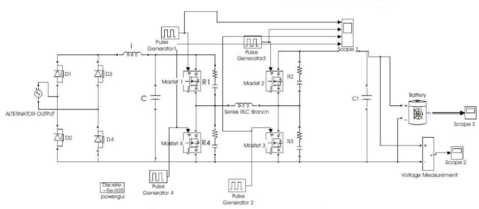
Figure 9. Simulation of AC-DC& DC-DC converter
Figure10 shows simulated AC-AC converter. Output obtained from Figure 9 gets boost up by DC-DC boost converter. In this condition the switch M2 & M3 is ON and M1, M4 is OFF. In this state, the current through the inductor rises from M2 →L1 →M3 →input. During this cycle inductor (L1) gets charged. The boosted DC output is converted into AC, which is discussed in the following section. Subsystem 1 in Figure 10 represents AC-DC converter & Subsystem 2 in Figure 10 represents DC-DC-AC converter
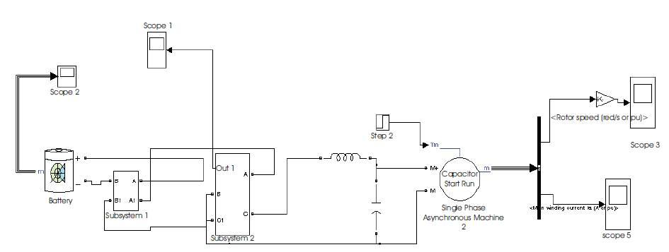
Figure 10. Simulation of AC –AC converter
DC Voltage from boost converter is converted into AC by inverter which is simulated as shown in the Figure 11.
Figure 12 shows the constant output voltage of 48V stored in battery.
Figure 13 &14 shows the firing pulses of Buck converter, depending upon the duty cycle the DC voltage has been bucked and stored in battery.
Figure 15 implies the required boosting factor pulse to boost 48volts to 220volts.
Figure 16 reflects the required PWM firing pulses for single PWM inverter. Pulses are generated by the comparison of sine and square waves.
Figure 17 implies the inverter output voltage of 98V, which is the stator voltage of single phase induction motor which drives the hybrid vehicle.
Figure 18 implies the stator current of single phase induction motor. The magnitude of stator current is 4A.
Figure 19 shows the speed of single phase induction motor which drives the hybrid vehicle in electrical mode. Here the designed speed of hybrid vehicle is 800 rpm.
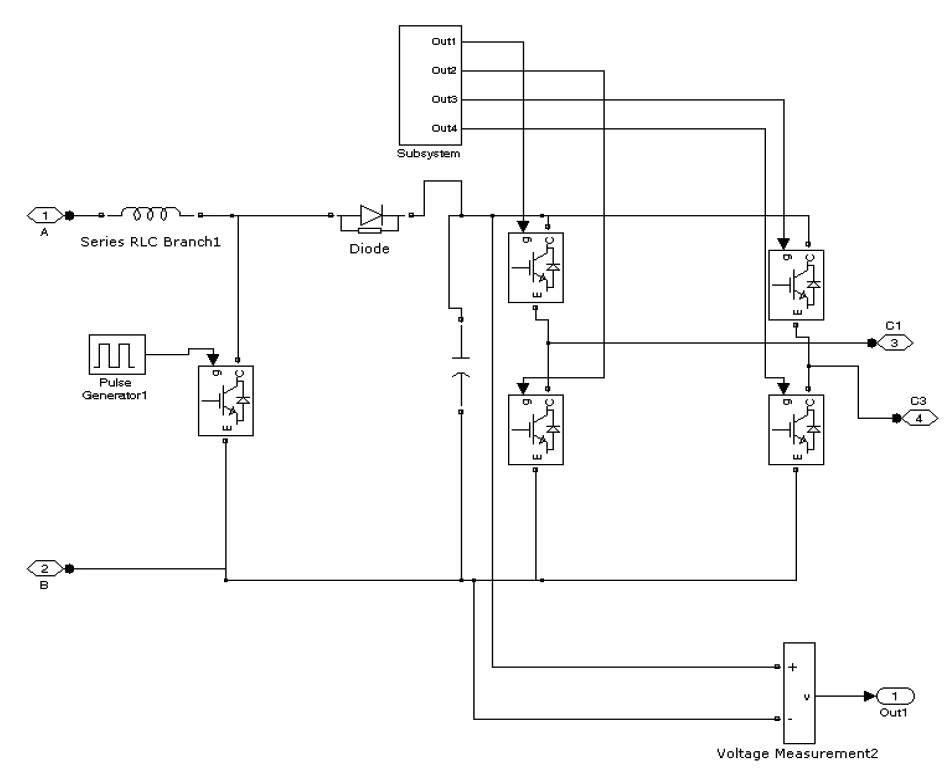
Figure 11. Simulation of DC -AC converter
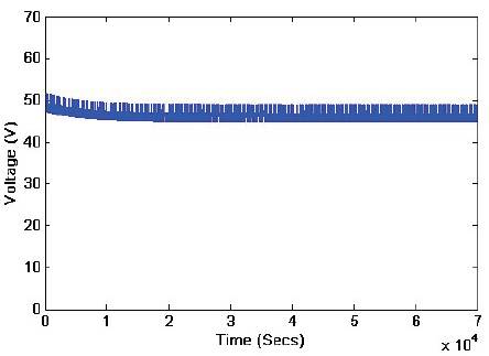
Figure 12. DC Voltage Stored in 48V Battery
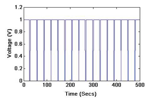
Figure 13. Firing pulses 1&2 of Buck converter
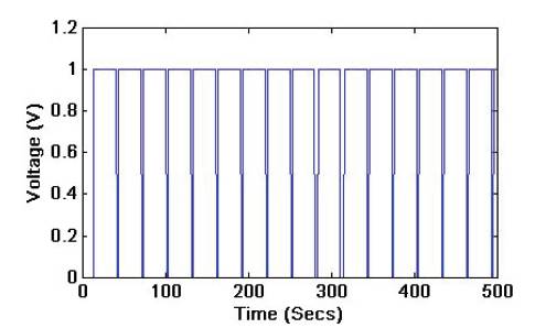
Figure 14. Pulses 3&4 of Buck converter
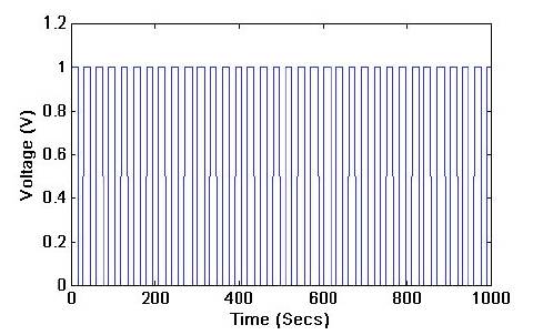
Figure 15. Firing pulses to Boost converter
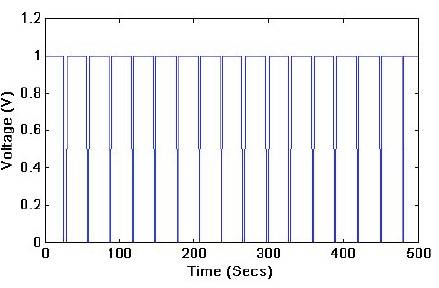
Figure 16. PWM firing pulses for inverter switches
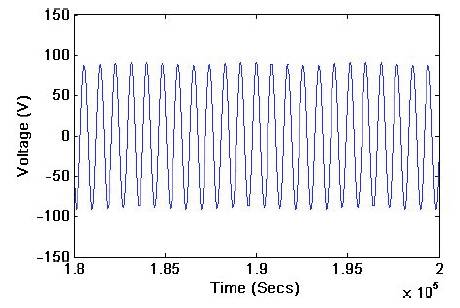
Figure 17. PWM Inverter output voltage
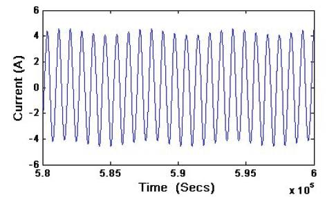
Figure 18. Stator current
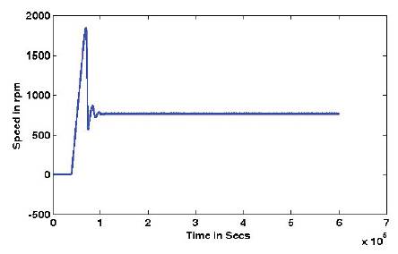
Figure 19. Rotor speed
AC to DC converter (rectifier) takes power from one or more AC voltage\current source of single phase or multiphase and delivers to a load (Figure 20). The output variable is a low ripple DC voltage or DC current. Many practical AC to DC converters use a voltage source with line frequency of 50 or 60Hz single phase or three phases. Normally the most preferred diode is IN4007. For higher ratings their advantages get diminished. In this project the authors recommend diode inbuilt bridge BR3510. The withstanding capability of this bridge is 50 to 1000V and 35A.
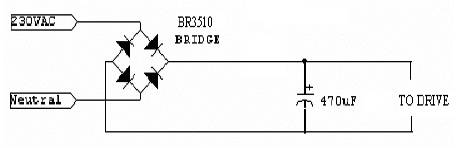
Figure 20. Rectifier Circuit
The function of MOSFET gate drive shown in Figure 21 is to issue gate signals to the MOSFET at regular intervals. Primarily the MOSFET gate drive is controlled by the signals issued from the PIC 16F877 controller. The IR2110/IR2113 are high voltage, high speed power MOSFET and IGBT drivers with independent high and low side referenced output channels. Proprietary HVIC and latch immune CMOS technologies enable rugged zed monolithic construction. Logic inputs are compatible with standard CMOS output, down to 3.3V logic.
The output drivers feature a high pulse current buffer stage designed for minimum driver cross-conduction. Propagation delays are matched to simplify use in high frequency applications. The floating channel can be used to drive an N-channel power MOSFET or IGBT in the high side configuration which operates up to 500 or 600 volts.
Gate drivers get 15V from the power supply for the internal network operation through pin 3. From U1 it gets PWM signal through pin 10 and 12 and from U2 it gets shut down signal through pin 11. Finally gate drivers generate 15V and gives its output to IGBT bridge circuit through pin 1 and 7.
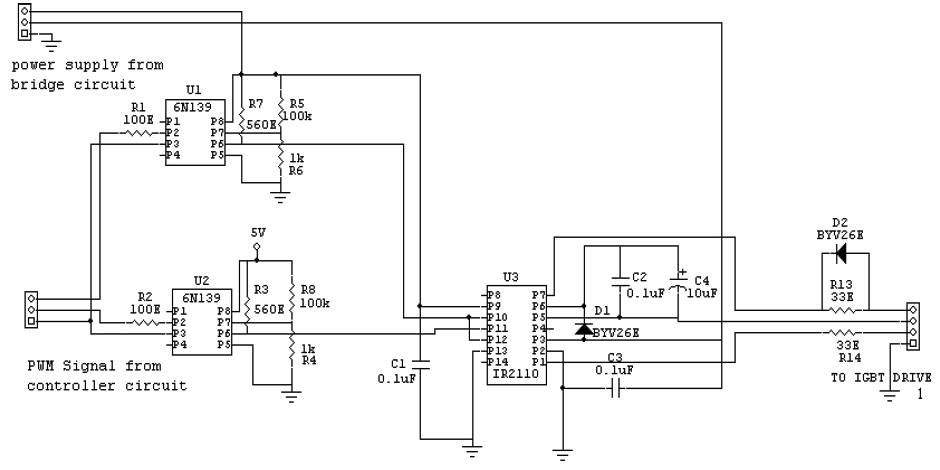
Figure 21. Gate driver Circuit
The PIC 16F877 Micro Controller shown in Figure 22 is the prime controller of this project. It controls the operation of various circuits associated in this project. The PIC 16F877 micro controller issues control signal to the IGBT drive circuit. It compares the actual speed feedback from motor with the desired speed entered via the computer. The various features present in this PIC16F877 helps to achieve an effective control over the induction motor.
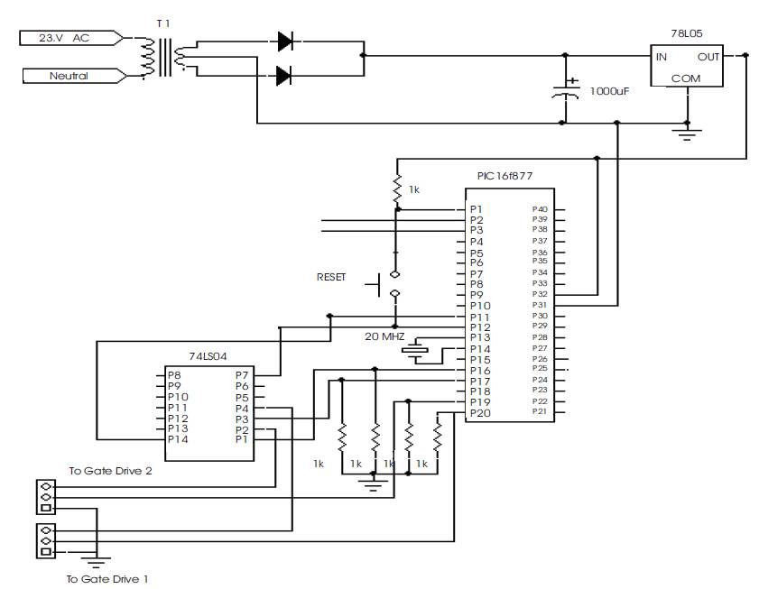
Figure 22. Controller Circuit
The bidirectional buck-boost converter shown in Figure 23 converts the DC input to pulsating DC in both direction.
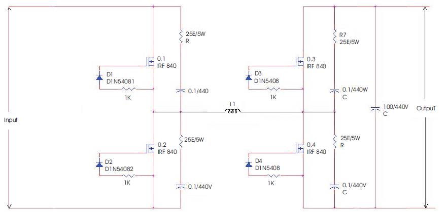
Figure 23. Bidirectional Buck-boost Converter Circuit
In this mode energy flow is input side to output side. In the first half the switch M1 & M4 is ON and M2, M3 is OFF. In this state, the current through the inductor rises from M1→L1→ M4→input. During this cycle inductor (L1) gets charged. The second half relates to the condition when the switch M1, M4 is OFF and M2, M3 is ON. In this stage the current flows from L1 to M2 to M4to Battery. Finally the energy in L1 is transferred to the output. The output voltage is constant depending upon the duty cycle.
In the input from the output the switch M2 & M3 is ON and M1, M4 is OFF. In this state, the current through the inductor rises from M2→ L→ M3→input. During this cycle inductor (L1) gets charged. The second half relates to the condition when the switch M1, M4 is ON and M2, M3 is OFF. In this stage the current flows from L1 to M1 to M4 to INPUT.
Figure 24 shows the output of alternator which is in sinusoidal nature. The prototype model has 22.8V pk-pk AC voltage which is fed to rectifier and boost chopper. The rectified DC output gets boost up by boost chopper, which is controlled by firing circuit. The firing pulses used to control the boost factor is shown in Figure 25.
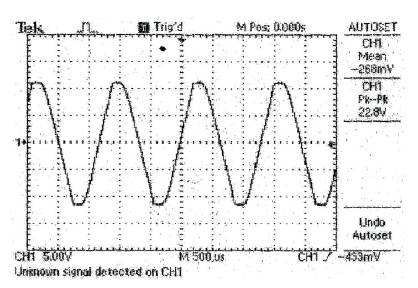
Figure 24. Input Voltage Waveform
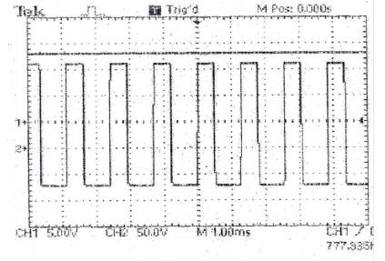
Figure 25. Output of Control circuit during Boost Topology
X-axis-Time Period in msec.
Y-axis-Voltage in volts.
Rectified output voltage gets buck and stored in battery and again boost up by boost chopper. The output of Buck- Boost converters is shown in the Figure 26. Figure 27 shows the experimental setup which has been analyzed and the output results are pull out using DSO.
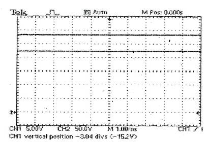
Figure 26. Output of Buck-Boost Converters
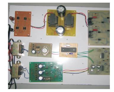
Figure 27. Expérimental Setup
Thus the bidirectional buck boost converter was designed, simulated using MATLAB software and implemented. The hardware model of the circuit is made. The output of the hardware circuit is compared with MATLAB simulated results and it is confirmed to be almost same. The output of the hardware is given to load and the system worked with respect to the design. It was witnessed that the output voltage remained constant with the variation of input voltage.