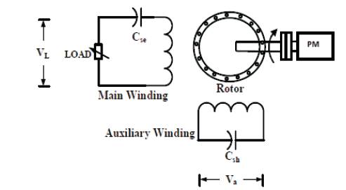
Figure 1. Basic Configuration of a Prime Mover Driven Series Compensated Single Phase, Two Winding Self Excited Induction Generator
Due to an inherently poor voltage regulation, the Self Excited Induction Generators (SEIGs) are incapable of supplying RL loads. One way of improving their voltage regulation is by series capacitance compensation. However, as the steady state load-ability limit of a compensated SEIG is increased, it is more likely to experience resonance due to change in either inductive loading or frequency or both. In this paper, a detailed analysis of resonating behavior of a single phase, two winding SEIG is carried out. The effects of resonance on the performance of SEIG are evaluated through performance characteristics obtained at the loads of different power factors. A steady state model of series compensated single phase, double winding SEIG is developed through MATLAB M file. The optimum excitation and compensation capacitances are selected by performing experimental tests on a 1 phase, double winding, 220/230 V SEIG.
Self excited induction generators carry an inherently poor voltage regulation. This is due to their incapability of being able to generate reactive power. In order to facilitate voltage build-up across the terminals of a prime mover driven SEIG, it has to supply reactive power from an external source. The most suitable mean of reactive power supply for SEIGs is by connecting capacitors across their terminals [1-4]. However, the shunt or excitation capacitors still do not cater to the reactive power compensation of load and hence do not have any bearing on the voltage regulation of the machine.
The voltage regulation of a SEIG may be improved to a great extent by various readily available means. The most suitable strategy in this regard is connecting a static series capacitor [5-8] in SEIG’s load winding circuit in various configurations. When operated with series compensation, the steady state load-ability limit of a SEIG is substantially increased due to improved voltage regulation. For low lagging pf loads, this creates conditions suitable for the inception of resonance in the SEIG circuit due to enhancement of operating range vis-a-vis maximum power output.
This paper articulates a detailed analysis on the resonating behavior of a single phase, two winding SEIG. In order to carry out the proposed analysis, a mathematical model of series compensated SEIG is utilized. The optimum excitation (shunt) and compensation (series) capacitances for the investigated SEIG have been selected experimentally through tests on a single phase, 220/230 V induction motor operated as SEIG. In order to get performance characteristics for the proposed study, the mathematical model of SEIG is implemented in a simulation program by generating program codes in M-file utility of MATLAB [9]. The basic configuration of SEIG connection is shown in Figure 1.
Figure 1. Basic Configuration of a Prime Mover Driven Series Compensated Single Phase, Two Winding Self Excited Induction Generator
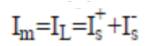
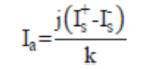
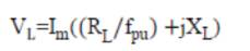
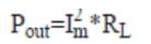
The necessary equations for the performance evaluation developed from the circuit model are as follows:
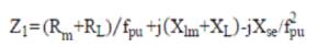
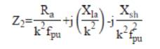
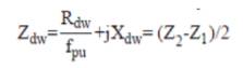
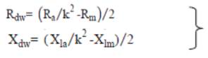
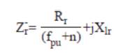
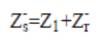
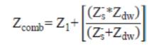
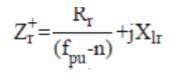
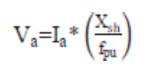
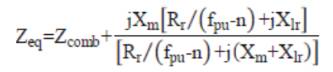
The performance calculations are done using equation (1)-(19). But, for the solution of these equations, the unknown parameters Vg , Xm and fpu are to be calculated. The procedure for calculation of Xm and fpu for the model of Figure 2 is initiated by writing loop equation and assuming fpu = n [10,11,14].
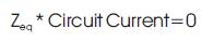
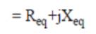
In equation (20), Circuit Current ≠ 0, thus the circuit impedance Zeq must be 0 in order that loop equation is satisfied. From this, a set of two non-linear equations given by (21) and (22) are obtained.
From equation (22),
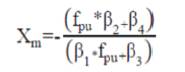
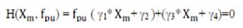
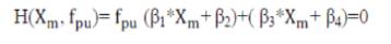
Substituting Xm from equation (23) in equation (21), m following quadratic expression is obtained in terms of fpu.
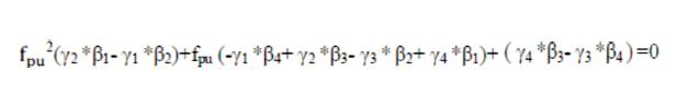
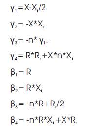
where, the constants γ1-γ4 and β1 - β4 are given in Appendix-I [10,11,14].
Assigning the real and positive root of equation (24) as fpu in equation (23) will yield Xm . It is worthwhile to mention here m that assumption made for the calculation of Xm above does not affect the accuracy of calculated values much but makes the calculation extremely simple.
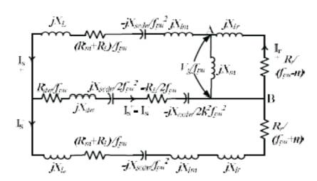
Figure 2. Steady State Circuit Model of a Single Phase Double Winding SEIG with Series Compensation
For the successful voltage build-up in a SEIG, the magnetizing characteristic of the induction machine has to be known. The characteristic provides variation of the air gap voltage Vg of the machine with respect to magnetizing reactance, Xm of the stator winding.
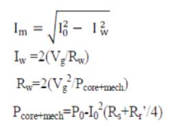
The magnetizing characteristic of machine may be estimated by synchronous speed test of the motor [11,12]. In order to obtain the required data from above test, the motor is driven on no-load and the stator windings are energised from the supply. By increasing the voltage in steps, the corresponding no-load current and power are noted. The no-load voltage is increased up-to 20% to 25% beyond the rated voltage of induction motor to get a number of readings. For each reading Vg and Xm are calculated from equations (25) and (26). The data obtained from the synchronous speed test is plotted to obtain variation of air-gap voltage against the magnetizing reactance.
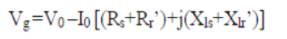
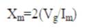
Where
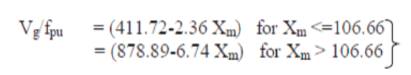
The piece-wise linearization of magnetizing characteristic of present machine yielded the expressions for Vg /fpu is given in equation 27 for different ranges of Xm .
Thus, having calculated the values of Vg , Xm and fpu , performance equations (13) to (17) are solved to obtain various characteristics of the SEIG model.
In order to assess the SEIG response for different loading conditions, a composite load model to simulate resistive as well inductive loads of different pfs has to be developed. For present analysis, all the loading conditions are simulated by (28).
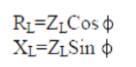
In (28) by substituting Cos ɸ according to the desired pf and with the load impedance ZL being varied from a very high to low value, the response of SEIG at different pfs from no-load to full load can be effectively simulated.
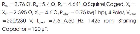
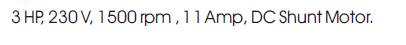
The motor and prime mover parameters are given in Appendix-II. The simulated and experimental results have been illustrated from Figures 3 to 12. All the characteristics have been obtained at a rated speed of 1500 rpm, i.e., 1 p.u. The external characteristics of SEIG at different shunt capacitances have been plotted in Figure 3. From the plots, a capacitance of 50 μF is found to be optimum as it fulfills the criteria of facilitating generation voltage of 230 V at no-load i.e., the rated voltage of SEIG. The other two plots of the characteristic clearly show that any capacitance less than 50 μ F or more is respectively generating no-load voltage less than and more than 230 V. Thus from the simulated and experimental results, which are in good agreement, a capacitance of 50 μF is found to be optimum for the investigated machine. Besides, as it is evident from the characteristics, for all the three shunt capacitances, the full load voltage regulation is not very encouraging.
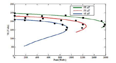
Figure 3. External Characteristics of SEIG at Different Shunt Capacitances Only.
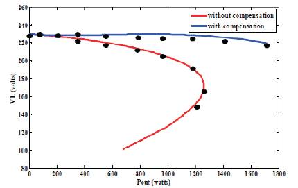
Figure 4. External Characteristic of SEIG with and without Compensation at Cex =50μF and Cse = 150μF.
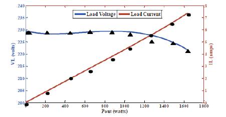
Figure 5. Variation of Load Voltage and Current at Unity pf with Cex =50μF and Cse = 150μF.
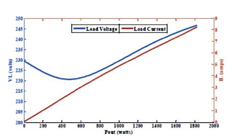
Figure 6. Variation of Load Voltage and Current at 0.9 pf (lagging) with Cex =50μF and Cse = 150μF
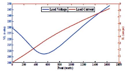
Figure 7. Variation of Load Voltage and Current at 0.8 pf (lagging) with Cex =50μF and Cse = 150μF.
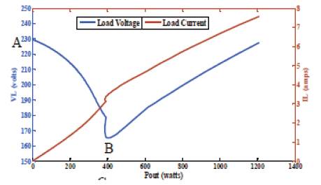
Figure 8. Variation of Load Voltage and Current at 0.7 pf (lagging) with Cex =50μF and Cse = 150μF.
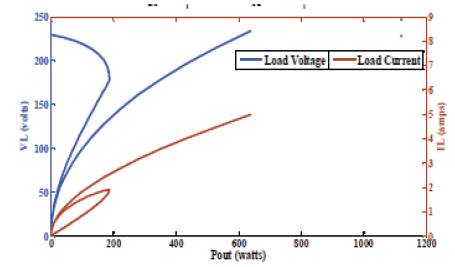
Figure 9. Variation of Load Voltage and Current at 0.6 pf (lagging) with Cex =50μF and Cse = 150μF.
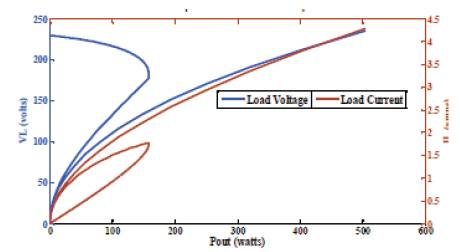
Figure 10. Variation of Load Voltage and Current at 0.5 pf (lagging) with Cex =50μF and Cse = 150μF.
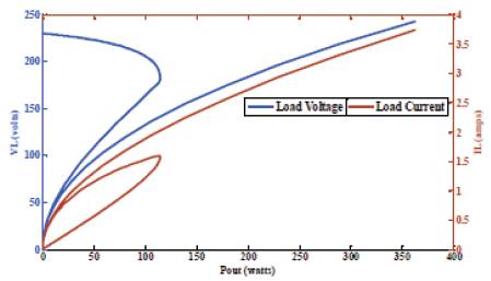
Figure 11. Variation of Load Voltage and Current at 0.4 pf (lagging) with Cex =50μF and Cse = 150μF.
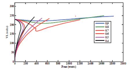
Figure 12. Load Voltages of SEIG Operating with Optimum Capacitances at Different Load pfs
In order to operate the SEIG in series compensation connection, a series capacitance of 150 μF is selected as optimum as it gives the best voltage regulation which is evident from Figure 4. For purely resistive load, SEIG is able to maintain constant load voltage of 230 V up-to the motor’s power rating of 1 h.p. while the voltage regulation for full range of the plot comes out to be about 4.7%. Compared to this, the non-compensated model gives out a full load voltage regulation of about 23%. Both compensated and non-compensated models are operated with optimum shunt capacitance of 50 μF. The load voltage and current of the compensated model for unity pf load can be seen in Figure 5.
With the same set of optimum capacitances, the SEIG is operated with lagging loads of different pfs. The results are illustrated from Figures 6 to 12. Figure 6 shows SEIG’s load voltage and current for inductive load of 0.9 pf. Here, it can be observed that for the early part of characteristic, the load voltage is decreasing marginally with load. However, beyond the output power of about 500 watts, the load voltage is interestingly increasing with load. This phenomenon is becoming more pronounced for increasingly inductive loading on SEIG. Figure 8 shows output voltage profile at a load pf of 0.8 lagging.
A detailed analysis of simulation data yielded by the model for inductive loading suggests that the sudden dip in voltage is caused due to the effective inductive reactance of SEIG circuit becoming equal to its effective capacitive reactance. Thus as soon as SEIG circuit starts to resonate, the voltage tends to drop abruptly. This tendency of load voltage is also reported in [13- 14], however no effort is made by the authors to explain the possible reasons for the behavior.
The effect of resonance on the load voltage can be more legibly explained from Figure 8, wherein the load voltage and current of SEIG are plotted against output power at an inductive load of 0.7 pf. The load voltage characteristic has been divided into three regions identified as A-B, B-C and the region beyond C. In the region A-B, load voltage is drooping with respect to the generated power just like the non-compensated model. However, as soon as the operating point of the characteristic reaches point B, the voltage drops suddenly from 178 V at B to 162 V, i.e., from B to C while the generated power decreases slightly. This abrupt drop in voltage is actually driven by a sudden increase in load current as it is evident from the load current curve. The SEIG perceives this sudden change in current as a transient fault or an overloading and hence immediately invokes its inherent self protection capability as voltage advances towards the collapse. However, since in the present case, the pf is not too low and the SEIG is able to rebuild the voltage after point C. After C, the load voltage is increasing with load.
The regions A-B, B-C and C onwards of Figure 8 are representative of the conditions before, during and after the inception of resonance in SEIG circuit. This is also the reason of the plot taking three different shapes. In the region A-B, the characteristic is drooping in nature as the XL is very high hence it effectively makes the circuit predominantly inductive. Region B-C corresponds to resonance as XL is nearly equal to XC . The abrupt increase in current at point C is due to inception of resonance. At point C wherein the characteristic attains its minimum value, XL is exactly equal to XC . Beyond point C, the circuit becomes predominantly capacitive as XL is further decreased along with RL to increase the loading. This is precisely the reason that the generated voltage is increasing with load beyond point C. Thus, before, during and after the inception of resonance, the SEIG windings work respectively in under, equal and over excited states.
It can be further observed from Figures 9 to11 that when the pf of load is decreased further, the voltage sag is progressively increasing. At the same time, inception of resonance in the SEIG windings is also getting initiated sooner in the generated power range. For the load pfs less than 0.7 the generated voltage profile is too staggered in nature for any practical application. Thus, below a load pf of 0.7, the present machine experiences a potentially stalling condition and hence such an operation should be avoided. A summary of SEIG resonating behavior is shown in Table 1.
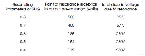
Table 1. Summary of the Resonating Behaviour of SEIG
The resonating behavior of a single phase, two winding self excited induction generators is investigated at different load power factors. The inception of resonance causes sudden drop in SEIG’s load voltage. For decreasing load pfs, the drop in load voltage increases and the inception of resonance occurs earlier in the output power range. It is observed that, when feeding inductive load, a SEIG has three regions of load voltage before, during and after the inception of resonance. In each of these regions SEIG windings work in under, equal and over excited states. This is precisely the reason due to which the SEIG voltage for inductive loads increase beyond a certain point with output power. However, if load pf is too low then the drop in voltage would be to the extent of SEIG getting stalled. Thus, operation of SEIG below a certain load pf should be avoided. For the present case, any load pf lower than 0.7 yields a load voltage profile which is too staggered for practical application. Thus for present case the optimum parameters of SEIG are identified as Cex =50μF and Cse = 150μF for a loads operating between unity to 0.7 lagging pf range. Below this range of pf, the load voltage profile of SEIG becomes too restrictive for practical applications.