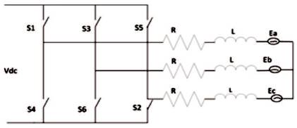
Figure 1. Equivalent Circuit Diagram of Voltage Source Inverter
This review paper is based on space vector based hysteresis current control in three phase PWM converter. In hysteresis current control technique, two, three or four level hysteresis comparator are used, which selects the appropriate inverter output voltage vectors by their switching phenomenon of vector based HCC, and it is used to control the current vector by keeping the current error vector in tolerance region. Through which the load gets desirable output current voltage. By keeping the zero phase difference between output current and voltage, acquires a high power factor by HCC voltage vector and this HCC voltage vector have some advantages over conventional HCC which are not to have interphase dependency and also maintaining constant modulation frequency or also reducing switching frequency. By this HCC, increase the system steady state performance and reducing dynamic response.
With the performance analysis of Hysteresis Current Controller high power factor of the three phase PWM converter is controlled by outer control loop of a system and current is controlled by inner control loop in HCC is used to control the current error vector [1,2].
In this paper, the aim is to get desirable output current at the load end. The current is controlled by space vector technique in HCC, and for two, three and four level Hysteresis comparator are used to get desirable output current to reduce switching frequency and to make a modulation frequency constant. It also overcomes the problem of interphase dependency which is to occur on conventional HCC method, [4].
Vector based methods are suggested to reduce the inverter switching frequency, [14], [19], [20]. The current error is measured in a space vector form and the vector based technique which is employed to keep the error vector in tolerance region. The vector based method systematically selects zero or non-zero voltage vectors to obey the current command vectors. By this technique, inverter switching frequency is reduced [20].
Figure 1 is a circuit diagram of a three phase VSI connected to a laod having back emf, resistance R, and inductance L. In each phase, it simulates induction motor. Now the three phase output voltage of the inverter (Vabc) is transferred to the stationary frame (α,β) by Clarke Transformation given as.
Figure 1. Equivalent Circuit Diagram of Voltage Source Inverter
“The VSI output voltage vector (Vn ) is caried out by the conduction state of inverter switches. Suppose Sa* =1, the upper switch is ON, Sa*=0, the lower switch is ON, similarly for leg B and leg C for VSI”.
Now the Voltage Vector is expressed by,

By equation (2), the inverter output voltage shows six nonzero voltage vector and two zero vector as shown in Table 1.
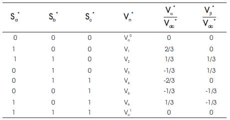
Table 1. Three Phase Switching States Respective of Voltage Space Vector and the α-β Values
Applying kvl on Figure 1 (a)
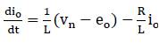
Vn =output vector voltage
Eo =back emf
Io =output current vector
Iref is current command vector and Ie is current error vector.

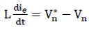
From equation (3) and (4), differential equation describing the current error vector is as follows,
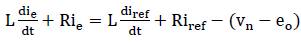
Equation (5) represents the current error vector having time constant T=L/R, and it influenced by Iref and its derivative with also command voltage vector and back emf (eo ). Now neglecting R in equation (5) and assuming o zero error in equation (5).
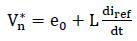
Rewriting (5) based on (6) leads to,
Equations (6) and (7) shows the information about back emf voltage vector [20].
Figure 2 is drawn with the help of equation 7 thus, discrete voltage vectors Vn * must be selected in order to obtain the desired optimal switching pattern.
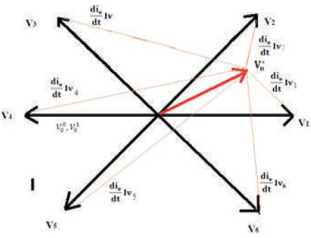
Figure 2. Current Error Vector when the Vector V * is located at Sector 1
In Figure (3), [3] having two feedback loop, outer loop is a voltage feedback loop and inner loop is hysteresis current control loop. The aim is to get controlled current based on vector taking current control loop for analysis [16] .
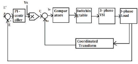
Figure 3. Control Block Diagram of a PWM Converter
The vector based hysteresis current controller having a set of summing point to compute the current error vector by Iref – Io . A set of comparators are used to define tolerance region, switching table is controlled switches of VSI and a coordinate transformation to convert three phase current signal to α,β frame. It is acquired by Clarks transformation to convert the three phase current signal into a space vector.
In conventional hysteresis current controller, a two level hysteresis loop is used for each leg having width δhys around each reference value of three phase current is shown in Figure 4 (a) [[5-11]]. Figure 4 (b) shows the tolerance region of conventional HCC.
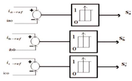
Figure 4 (a). Schematic Diagram of Conventional HCC
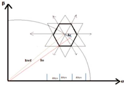
Figure 4 (b). Tolerance Region of Conventional HCC
When the inverter current becomes greater or less than the reference value by the hysteresis band δhys , the inverter leg in the corresponding phase is switched to the negative or positive direction correspondingly Conventional HCC has a mutual interaction between phase current, if the load neutral is isolated or has variable modulation frequency [3],[4] which is a disadvantage.
A space vector based HCC is to avoid the drawbacks of the conventional HCC such as interphase dependency by space vector to convert three phases into stationary α- β frame by Clark's transformation [12-14].
This space vector HCC having three level hysteresis comparators are shown in Figures 5 (a), and 5 (b), and the overall bandwidth of three level hysteresis comparator is equal to δ+Δδ with the switching table.
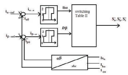
Figure 5 (a). Schematic Diagram of Vector Based HCC
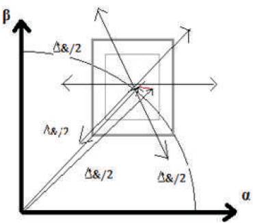
Figure 5 (b). Tolerance Region of Vector Based HCC
Square center shows current vector reference at every instant. If the inverter current touch the surface of square region, then the inverter output voltage will be selected as shown in Table 2 to keep the current error vector in tolerance region. This method reduces the switching frequency of inverter, but here is some problem which is shown in switching table is the presence of redundant situations in control action lead to non-optimal switching pattern in some place [27].
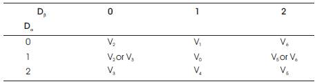
Table 2. Switching Table for Space Vector Method II
In the proposed method, space vector HCC using multilevel hysteresis comparators is used. In this, if the actual current crosses the tolerance region on one side, then a new voltage vector with opposite component on that side are to be applied to keep current error vector in tolerance region [21-23]. Figures 6(a) and (b) shows its working. If the actual current crosses top side of the tolerance region, the next inverter voltage must have a smaller β component to keep the tracking error inside a tolerance region.
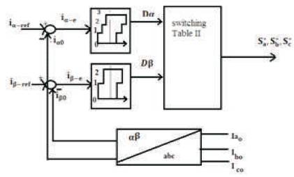
Figure 6(a). Schematic Block Diagram Proposed HCC
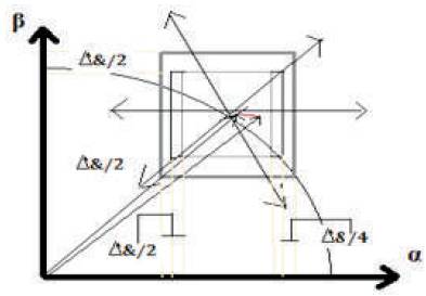
Figure 6(b). Tolerance Region Proposed HCC
A space vector HCC have two hysteresis comparatorsone is μ four level hysteresis comparator and other is three level hysteresis comparator β shown in Figure 6(b). The proposed vector based current controller implements four and three level comparator in stationary α-β frame which is shown in Figure 6 (a), the tolerance region of α and β axis is δ+Δδ shown in Figure 6 (b) [24-26, 28,30].
The selection of hysteresis bandwidth comparator is depending on the accuracy requested from current controller. If the hysteresis is smaller than the current error vector it is restricted in a small region which caused more oscillations and also increased switching frequency. It is important to maintain hysteresis bandwidth not too small and also not much large to cause the error vector. Increase switching frequency makes optimal switching operation. At each instant, digital output of the hysteresis comparators Dα and Dβ determine the discrete state of inverter output voltage according to Table 3.
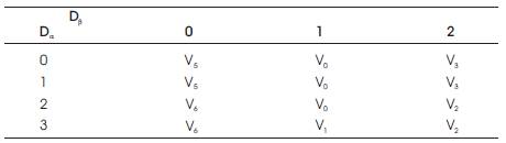
Table 3. Discrete State of Inverter Output Voltage
The comparator output varied, w.r.t changes in inverter output voltage vectors changes in inverter output voltage for keeping error vector inside a two internal and one external square tolerance region shown in Figure 6(b) [21, 29].
In the proposed vector based hysteresis current controller method, a switching having four states optimal and voltage vector sets have six sectors having 60o of a fundamental frequency and inverter switching frequency is reduced by the selection of zero and non-zero voltage vector systematically by space vector modulation. The zero state is Voo voltage vector is equal to V1 , V3 or V5 or for V01 the inverter states come from V2 , V4 or V6 . By this phenomenon, switching frequency is reduced [15-18].
This review paper has discussed the difference in the switching frequency, hysteresis bandwidth, and current control method and by controlling the current improving power factor. The best method, vector based hysteresis current controller is presented. This method has two multilevel Hysteresis comparators in α and β axis to divide the stationary complex into six 60o sectors. The position of the desire voltage is determined on the basis of digital output hysteresis comparators which are needed to achieve an optimal switching pattern. The proposed space vector based hysteresis current controller is best method as compared to conventional hysteresis current controller and vector based method I. The main disadvantages of conventional HCC is “interphase dependency ” and having variable modulation frequency as well as higher switching frequency. To overcome this problem, vector based HCC method is used but it has also some problem of “redundancy” which is shown in Table 2. Therefore after this, the method vector based HCC III is used which reduces switching frequency and also dose not have interphase dependency.