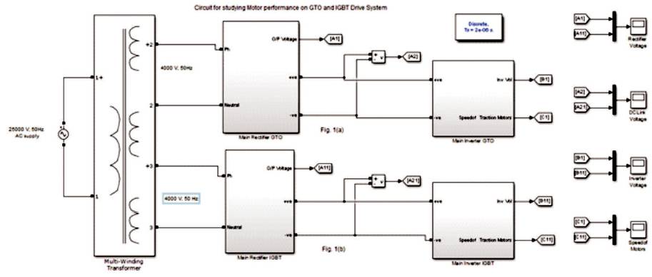
Figure 1. Proposed Circuit Diagram for Studying SCIM Performance with GTO and IGBT Drive Systems
The electric locomotives of Indian Railways currently use Gate Turn- Off Thyristors for traction drive systems. Though they are fast switching devices, they produce lot of harmonic ripples in the output voltages and currents. The snubber circuits of Gate Turn-Off Thyristors are also bulky. Comparatively, Insulated Gate Bipolar Transistors produce less harmonic ripples and also reliable fast switching devices capable of handling voltages and currents of the range 5kV and 1kA respectively. Research has also proved that, Insulated Gate Bi-Polar Transistors are also an efficient switching devices in high voltage/power applications like electric traction. The simulation studies of performance of the Squirrel Cage induction motors with Gate Turn-off Thyristors/Insulated Gate Bi-Polar Transistor as switching devices are presented in this paper.
Three-phase alternating current locomotives of Indian Railways of the class WAP-5, WAP-7 and WAG-9 use Squirrel cage induction motor as traction motors wherein the locomotives WAP-5 and WAP-7 are constant power passenger locomotives and WAG-9 is a constant torque freight locomotive. The six traction motors of WAP-7 and WAG-9 are divided into two sets of three traction motors connected in parallel and each set is driven by a set of three 2-pulse bridge inverters where fundamentals are shifted by a phase difference of 120˚ [1]. The input converter is a set of two 4-pulse bridge rectifier connected in parallel. The input voltage to the rectifier is 4kV, 50Hz, 1- phase AC stepped down by the 25kV/4kV transformer where 25kV, 50Hz AC voltage collected by the Pantograph. The main converter, motor inverter and auxiliary converters use Gate Turn-Off Thyristors as switches [1]. The Insulated Gate Bipolar Transistors have many inherent advantages over the Gate Turn-Off Thyristors for high power applications. A comparative study of the characteristics of Squirrel Cage induction motors driven by three-phase inverter with Gate Turn-Off thyristors and Insulated Gate Bipolar Transistor are carried out in this paper.
The power conversion in a converter is achieved by means of switches. These switches should have the characteristics like capability to handle high currents and voltages and also must be capable of fast switching, functioning at high frequencies, high reliability, compact in size, easy to construct, less cost and above all it should have low switching losses [2]. The switch which has the entire above listed characteristic is called an 'Ideal Switch'. None of the switch used in the power converters are ideal and each kind of switch has its own advantages and disadvantages. For an electric locomotive drive, the switch should have very high reliability as, failure of the switching devices would cause disruption in traffic flow. In this section, a detailed comparison is drawn between a Gate Turn-Off Thyristors and Insulated Gate Bipolar Transistor.
A Gate Turn-Off Thyristor is a type of thyristor that has the capability of getting turned off on the application of a negative gate pulse. A GTO incorporates most of the advantages of the conventional thyristors, and the highvoltage switching transistor. It is a PNPN device capable of being switched on by the application of a small positive gate-current and also capable of being switched off by the application of a negative gate-current. A GTO that is required for traction application may be of the rating 4000 V, 3100 A and may require a -750 A gate-current to turn it OFF. This advantage of GTO allows the construction of inverter circuits without the bulky and expensive forced commutation circuits for turning the device OFF. The GTO also has faster switching speed and can withstand high voltage and current. GTO with symmetric or asymmetric voltage blocking capabilities are available. The use of asymmetrical GTO requires a diode in series with each GTO to gain the reverse blocking capability. Asymmetrical GTO offers more stable temperature characteristics and low on-state voltage as compared to a symmetrical GTO. The function of the snubber circuit is of importance in a GTO as, the GTO turn-off characteristics depend on the snubber circuit. The snubber circuit helps in increasing the peak gate controllable current capability, which takes in the current diverted from the GTO, when there is a high inductive load which would otherwise have caused losses in GTO itself and the snubber capacitance suppresses the rate of rise of forward voltage following the turning off of the device thereby preventing of maltriggering of GTO. This means that the snubber circuit of a GTO has to be large and bulky. The snubber power dissipation is also large. This becomes a disadvantage as the Converter Unit itself would become bulky.
Another disadvantage with GTO is its susceptibility to damage by excessive voltage and current. This particular problem can be faced in a Locomotive in case of wheel spin or pantograph bounce as discussed in the above section. The GTO also has high surge capability and hence protective equipment is required to protect it. Any attempt to extinguish the high surge by means of Gate Turn-off control would result in destruction of the device itself [3]. Hence, from the Railways point of view, a more reliable switching device would be preferable.
The Insulated Gate Bipolar Transistor incorporates itself in the best properties of power MOSFETS and transistors. The IGBT has the input characteristic of a MOSFET and output characteristic of a transistor which means, it has high input impedance and low on-state conduction losses [4]. It is a voltage controlled device and hence, can be used in a voltage source inverter. The IGBT has high efficiency and fast switching capability. Large IGBT modules having many devices in parallel have current handling capacity of hundreds of Amperes and blocking voltages of order 6000 V, which equates to few hundred kilowatts [5]. The IGBT has an inbuilt snubber circuit and hence does not require bulky external snubber circuits as in the case of GTO. The IGBT also has very large safe operating area. It also has low conduction losses. The ability to control the turn-on and turn-off times by controlling the gate current through appropriate series of gate resistance reduces the use of snubber circuits for turn-on and turn-off. The IGBT can also work at high ambient temperatures. It can also be used at lower operating frequencies if required. All these capabilities of IGBT makes it an ideal switch for traction power converter application [6,7]. Hence, the existing circuit will be re-designed with IGBT as the switching device and simulated with MATLAB Simulink to draw up a comparison with GTO Converters.
The design of circuit for comparative study of performance of the AC traction motors on GTO and IGBT drive system is described in this section. For the threephase Squirrel Cage induction motor drive, the traction rectifier will be a set of two 4-pulse bridge connected in parallel. The DC link consists of LC-filter to filter out the harmonics. The DC link will be connected to a three-phase inverter to drive a pair of traction motors. Both the drive systems will be connected to a high impedance transformer with secondary voltages of 4000 Volt. The proposed circuit is shown in Figure 1 and the details of inverter connected motors is shown Figures 2 (a) and 2(b).
Figure 1. Proposed Circuit Diagram for Studying SCIM Performance with GTO and IGBT Drive Systems
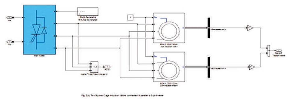
Figure 2(a). GTO Inverters connected to SCIM
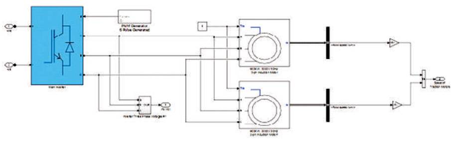
Figure 2(b). IGBT Inverters connected to SCIM
Simulation studies were carried out with both GTO and IGBT as a switch to compare the results.
The circuit is broken up into three parts for analysis namely
(a) Rectifier
(b) DC Link
(c) Inverter
The main rectifier is a 4 – pulse bridge with GTO as a switch in Figure 2(a) and IGBT as a switch in Figure 2(b). Two 4- pulse bridges are connected in parallel to form one unit of traction rectifier. The input to the rectifier is 4000 V, 50 Hz AC supply fed from multi-winding transformer to which a primary Voltage of 25kV is fed from a voltage source. The secondary windings are designed to give output of 4kV. The output of the rectifier is fed to the DC link.
The traction rectifier output is connected to the DC link. The DC link consists of a capacitor bank of 815μF and 11.41 mF connected in parallel to filter out the harmonics in the DC voltage. A diode is connected in the DC link to ensure unidirectional current. The output of the DC link is connected to the traction inverter.
The traction inverter is a 6-pulse bridge inverter circuit which is capable of generating sine waves displaced by a phase difference of 120˚. The pulses for GTOs and IGBTs are delivered by means of a sinusoidal pulse width modulated generator. The output of the traction inverter is fed to the traction motors. GTO is used as the switching device in the traction inverter in Figure 2(a) and IGBT is used as switching device in the traction inverter in Figure 2(b). The system is designed in such a way that, a traction inverter will supply power to two traction motors connected in parallel. Thus, for a 6-axle locomotive, there will be three traction inverters feeding the traction motors. This will ensure 100% reliability in operation of the locomotive. The circuit diagram shown in Figure 1 is simulated using MATLAB Simulink.
The Squirrel Cage induction motor rating of 900 kW is used as traction motor in this simulation. The locomotives of the variant WAG-9 use SCIMs rated at 850 kW currently. The ratings and other parameters of the SCIMs used are listed in Table 1.
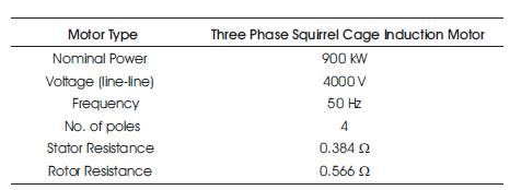
Table 1. Motor Parameters
The results of the simulation are discussed in this section. The results are analysed with respect to the rectifier output voltage, the DC link voltage, stator input voltages and the speed achieved by the motors.
The input 25kV, 50 Hz, 1-φ, AC are shown in Figure 2(a). The output voltage waveforms for GTO rectifier and IGBT rectifier are shown in Figure 3. A pulsating DC voltage waveform with a magnitude of 4000 V is observed in both the case studies. The harmonics are visibly reduced in the rectifier which made use of IGBTs as switches as can be seen in Figure 3. This reduction in harmonics would result in reduced energy losses in the form of heat generated with harmonic content voltages and currents in the components like the capacitors and resistors used in the DC link. This reduction in harmonics would also reduce the ratings of capacitors and resistors used in the RC filter to filter out the harmonic content in the voltage and current waveform.
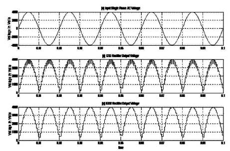
Figure 3. Input and Rectifier Output Voltage Waveforms
As the snubber circuits required by the IGBT is significantly reduced in size as compared to the one required by the GTOs, the size of the rectifier unit will also reduce. The cooling of the unit will also be easier to manage as the heat energy generated will be less in magnitude in an IGBT rectifier. The Waveforms for DC link voltages observed in simulations carried out with GTO and IGBT as switches in rectifier are shown in Figure 4. It can be clearly seen from the waveform that, steady state is reached faster in IGBT rectifier fed DC link at about 0.32 seconds as compared to 0.35 seconds taken by GTO rectifier. From the graph, it can also be inferred that, the magnitude of DC link voltage is higher in the case of IGBT rectifier as compared to GTO rectifier though the value of capacitor bank in both the DC links are same. This can be attributed to the reduction in harmonics and as a result, efficiency is improved as the losses are reduced.
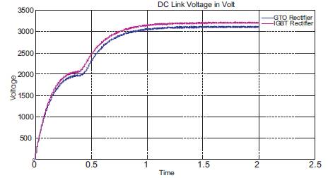
Figure 4. DC Link Voltage Waveform
The inverter output voltages observed for both GTO inverter and IGBT inverter are shown in Figures 5(a) and 5(b) respectively. The inverter produced sinusoidal waveforms with PWM firing at an operating frequency of 60 Hz. The inverter can work in the frequency range of 30 to 120 Hz, so that the speed of the traction motors can vary resulting in increase or decrease of speed at the wheel of the locomotives. The harmonics are considerably reduced in the IGBT inverter as compared to the GTO inverter. The reduction in harmonics in the inverter output is very important, as it will directly affect the performance of the traction motors and a reduced level of harmonics leads to lesser noise, reduced wear and tear of insulation of motors, reduced torque ripples and lesser vibrations. The control of the traction motors by means of variable voltage variable frequency is achieved very smoothly in the case of IGBT inverter. The frequency of operation of the inverter is changed to match the new speed required by the traction motors by just changing the frequency of the three-phase sine waves in the PWM generator. The overall performance is better for IGBT inverter both in terms of control and efficiency of operation.
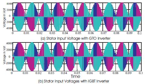
Figure 5. Inverter Output Voltage Waveforms
The speed developed by the traction motors when worked by GTO inverter and IGBT inverter is shown in Figure 6, when operated at frequency of 60 Hz. As it can be seen, the traction motors reach the rated speed faster when fed by IGBT inverter. The acceleration from zero speed to rated speed is smooth. The time taken for acceleration of the motor is also less in IGBT inverter fed motors. As the voltage control is smooth in IGBT inverter, the problem of slipping of wheels can also be overcome effectively as time taken for acceleration is also less. This gives better adhesion at the wheels and the grip on rails will be improved.
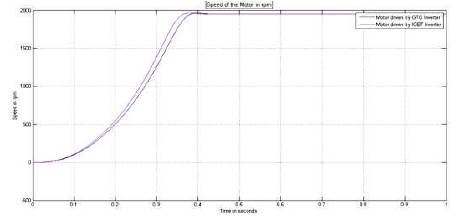
Figure 6. Speed Developed by Traction Motors
From the above analysis of the results and the simulation studies carried out in MATLAB Simulink, it can be concluded that the performance of the IGBT based rectifier and inverter is superior as compared to the GTO based converter systems. The efficiency of operation is improved markedly mainly because of the reduction of the snubber circuit, reduction in harmonics thereby reduction in heat produced in the devices, also better conduction is shown by IGBT. This effect of improvement of efficiency of operation and smooth transition of voltages is observed in the speed developed by the traction motors. The acceleration time of the Motors is reduced and hence, the motors reach the rated speed in a very less time. Also the detioration in insulation of motors will reduce, as the harmonics are reduced resulting in lesser eddy currents. As the performance of the proposed circuit is better when compared to the currently operating circuit GTO drives in locomotives in India, the use of IGBT in converter systems in future locomotives is highly recommended.