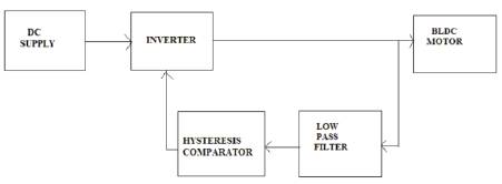
Figure 1. Block Diagram of the BLDC Motor
This paper presents the BrushLess Dc (BLDC) motor sensorless control system. The sensorless techniques are based on a hysteresis comparator, and a potential start-up method with a high starting torque is suggested. The hysteresis comparator is used to compensate for the phase delay of the back-EMFs due to a Low-Pass Filter (LPF) and also prevent multiple output transitions from noise or ripple in the terminal voltages. The rotor position is aligned at standstill for maximum starting torque without an additional sensor and any information of motor parameters. Also, the stator current can be easily adjusted by modulating the pulse width of the switching devices during the alignment. The life time of the motor is improved by using the sensorless technique [1].
In recent years, the BrushLess Dc (BLDC) motor is receiving much interest in automotive applications, due to its high efficiency, compact size, and lower maintenance when compared to a brushed dc motor. In order to obtain an accurate and ripple-free instantaneous torque of BLDC motor, the rotor position information for stator current commutation must be known, which can be obtained using the Hall sensors mounted on a rotor. This results in a high cost as well as poor reliability, which are serious problems at the vehicle applications. To cope with the above mentioned restriction, many position sensorless algorithms have been considered as potential solutions [3].
To satisfy these requirements, many potential algorithms are developed. These developed algorithms are restricted in an automobile fuel pump application which requires good reliability, a wide speed range from 3000rpm to 9000rpm, fast start-up and high starting torque for the sensorless BLDC motor drive systems. This paper presents a sensorless control based on a hysteresis comparator of terminal voltage and a potential start-up method with a high starting torque. The hysteresis comparator is used to compensate for the phase lag due to the low pass filter and also to prevent multiple output transitions from noise or ripple in the terminal voltages. It is able to improve both of the performance and reliability for the sensorless BLDC motor drive system [2].
With respect to the data collected from the IEEE transactions, it is noted that many position sensorless algorithms have been considered as potential solutions. The zero-crossing of the back-EMF measured from the stator winding is detected and the commutation points can be estimated by shifting 30 from the zero crossing of the back-EMFs. The performance of the sensorless drive deteriorates with the phase shifter in the transient state.
Also, it is sensitive to the phase delay of the Low Pass Filter (LPF) especially at the high speed. Several phase shifters which are compensated for phase error induced by the LPF of back-EMFs are proposed. They require an additional compensation circuit including the timers. The position information is extracted by integrating the back- EMF of the silent phase. This method has an error accumulation problem at the low speed.
The sensorless control techniques using the Phase-Locked Loop (PLL) and the third-harmonic back-EMF are suggested [9]. The motor commutation drifts away from the desired phase angle, due to the conduction of the freewheel diode. Furthermore, the drift angle varies from the motor parameters, speed, and load conditions change. The improved sensorless controller by removing the effect of the freewheel diode conduction is suggested in this paper, Access of the motor neutral point is required, which will complicate the motor structure and increase the cost.
Some approaches use the zero crossing points of threephase line-to-line voltages, so that they coincide with six commutation points. Although the commutation signals can be obtained without any phase shifter, the phase delay due to the LPF could not be considered and the multiple output transitions of the comparator may occur from the high frequency ripple or noise in the back-EMFs. The zero-crossing point of the back-EMF for generating proper commutation control of the inverter is calculated by sampling the voltage of the floating phase without using the current and position sensors [10] [12].
For the BLDC motors, the Hall effect position sensors are usually used to identify, which phase is to be commutated to maintain the electrical synchronism. The Hall effect is the production of a voltage difference (the Hall voltage) across an electrical conductor, transverse to an electric current in the conductor and a magnetic field perpendicular to the current.
For high performance drives, high-resolution optical encoders or resolvers are typically used. The most popular type of encoder is the optical encoder, which consists of a rotating disk, a light source, and a photo detector (light sensor). The disk, which is mounted on the rotating shaft, has coded patterns of opaque and transparent sectors. As the disk rotates, these patterns interrupt the light emitted onto the photo detector, generating a digital or pulse signal output.
Various methods of sensorless operation for BLDC motors are also used to detect the position of the rotor of the BLDC motors. In flux calculation based methods, the flux linkage is estimated from measured voltages and currents and then the position is predicted by polynomial curve fitting [8].
The Signal Injection Method and inductance based method are also widely used. Based on the current, the rotor pole sign is estimated. This method detects the difference of the saturation level based on the sign of rotor magnet flux. Two voltage pulses with opposite signs are applied for a predetermined time for the purpose. Then, maximum current is measured at the end of the applied voltage pulse. The difference between the positive and negative maximum currents is calculated to find out which pole is close to the corresponding phase. For other phases, the same procedure is repeated. The resultant of the three signs provide information regarding, which phase should be excited first. This method provides 60º (electrical) resolutions at standstill.
Drawbacks of the existing systems are,
In BLDC motor, the position of the rotor is estimated by using the hysteresis comparator. The hysteresis comparator is used to compensate the phase delay of the back-EMFs produced in the system. Thus, it reduces the pulsating torques in drive which may cause oscillations in the drive system. Overall copper losses are reduced by using the hysteresis comparator. Figure 1 shows the Block Diagram of the BLDC Motor.
Figure 1. Block Diagram of the BLDC Motor
By using this proposed system, life time of the device will be improved. Control of over speed is carried out at wide range, at low cost. Interference from the multiple effects are neglected. The commutation phase lag is significantly reduced by it and it gives high reliability [4,5] [14].
The proposed system has wide applications in areas such as
The comparator is the most fundamental building block of a mixed-signal design. The hysteresis comparator has two fixed threshold levels and the output changes its state only when one of them is crossed.
The system consists of the LPFs for suppressing the high switching frequency ripples, hysteresis comparators for generating three-phase commutation signals, and a gating signals generator for generating six PWM signals. After sensing the three-phase terminal voltages, each of the three-phase terminal voltages is fed into an LPF to suppress the high switching frequency ripple or noise. As only two phases of the BLDC motor are energized at any time, the back-EMF can be measured from its terminal voltage in the period of an open phase (60°). During the two-phase conduction period (120°), the only difference between the back-EMF and its terminal voltage is a stator impedance voltage drop, which may be considerably small when compared with the dc voltage source. Therefore, the waveform of the terminal voltage is nearly the same as that of the back-EMF. The terminal voltages can be used to detect the commutation points of the BLDC motor instead of the back-EMFs at the proposed sensorless control.
In the BLDC motor, only two phases of the three-phase stator windings are excited at any time by utilizing alternative six excited voltage vectors V1-V2. That is why the current can flow into only two of the three windings and commutated every 60° of electrical angle. At standstill, the initial rotor position is aligned into one of six positions that are determined by the six excited voltage vectors to energize two phases of the BLDC motor. As it is well known, the deviation of these voltage vectors is every 60° of electrical angle. The stator flux is not orthogonal to the rotor flux generated by the permanent-magnet at the beginning of the start-up point if the conventional alignment method is used. Thus, the initial motor torque can't obtain the maximum value at this time.
Also, the stator winding incurs a high uncontrollable current by means of the fixed dc power supply and motor parameters. This might damage the stator winding of the motor if the active time for aligning a rotor position is too long. The conventional start-up method reveals some unexpected drawbacks that might degrade the performance of the BLDC motor. To overcome these restrictions, a simple start-up method not only to achieve the maximum starting motor torque but also to control the stator current is proposed.
Unlike the case in the conventional method where only [11] two stator windings are excited, all three stator windings are energized in the case of the proposed startup scheme by using a specific initial voltage vector Vi (1,0,0). As the rotor is located between voltage vector and the voltage vector is orthogonal to Vi, it is chosen as the next applied voltage vector in order to achieve maximum starting motor torque at start-up. It should be noted that the amplitude of the stator current for alignment of the rotor position can be easily adjusted by modulating the pulse width of the switching devices. The magnitude of the stator current can be easily governed by adjusting the duty cycle, which can be decided by considering the initial torque which is required at alignment. This method can prevent a surge of current which will damage the motor. In the case of utilizing the conventional method, the robust with motor parameter will be changed. The motor may rotate reversely during the alignment according to the rotor position before the alignment. However, as a maximum reverse rotating angle is only 90 mechanical degrees, it does not have the influence on a fuel pump operation. As the sensorless scheme is not selfstarting, the motor should be started and can be brought to a certain speed at which the zero-crossing point of the back-EMF can be detected. Figure 2 shows the Plot of phase shift after compensation. Figure 3 shows Rotor Position Estimation.
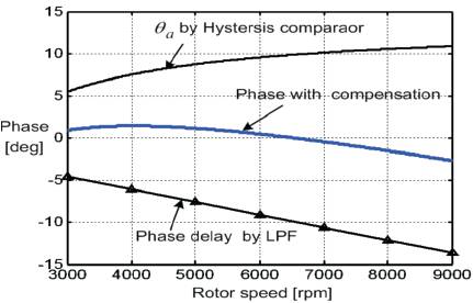
Figure 2. Plot of phase shift after compensation
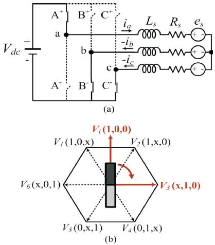
Figure 3. Rotor Position Estimation
Simulink is a block diagram environment for multi domain simulation and Model-Based Design. It supports the system-level design, simulation, automatic code generation, and continuous test and verification of embedded systems. Simulink provides a graphical editor, customizable block libraries, and solvers for modeling and simulating dynamic systems. It is integrated with MATLAB, enabling to incorporate with MATLAB algorithms into models and export simulation results to MATLAB for further analysis. Figure 4 shows the simulation block diagram of the BLDC Motor Block and Figure 5 shows the rotor speed waveform.
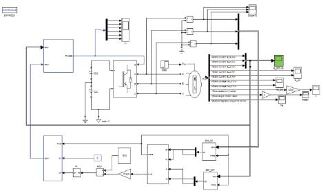
Figure 4. Simulation Block Diagram of the BLDC Motor Block
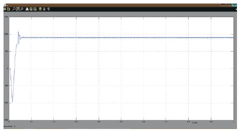
Figure 5. Rotor Speed Waveform
The simulation [6,7] [13] diagram shows the BLDC motor block, hysteresis comparator block and inverter switches. The inverter is connected with the motor block. The output of the motor is connected with the hysteresis comparator. The output of the three phase motor is converted into two phase by parks transformation. Hysteresis comparator compares the two phase signal with the reference signal and the controlled output signal is given to the inverter switches.
This paper presents a sensorless control based on a hysteresis comparator of terminal voltage and a potential start-up method with a high starting torque. As the maximum commutation phase lag is significantly reduced from -13° to -3° by adjusting both the resistance ratio, and the output voltage level of the hysteresis comparator, the commutation signal is nearly in phase with the back-EMF. If a peak of ripple voltage in the terminal voltage is within the hysteresis band +1V regardless of magnitude of the terminal voltage, it can prevent the multiple output transitions at a hysteresis comparator by high frequency ripples in the terminal voltage. After aligning the rotor position for achieving the maximum starting torque, the BLDC motor accelerates from a standstill up to a nominal speed within 1.2sec. The magnitude of the stator current for aligning the rotor position can be easily controlled by modulating the pulse width of specific switching devices.