Figure 1. General layout of electric locomotive
This paper describes about the single and double stage control of DC traction motor. DC series motors provide excellent control of speed for acceleration and deacceleration and it is used for their simplicity, reach of application and favourable cost. In India, still most of the locomotive run with DC motor only, because DC series motor has high starting torque with load, hence it is preferable for traction purpose. The invention relates generally to traction motor control systems, and relates more particularly to locomotive traction motor suspension and current control systems. This case describes controlling of single and double stage of DC series traction motor. The simulation and experimental results are done by using MATLAB software package and the comparison results are shown.
The first railways were powered by steam engines. Although the first electric railway motor came on the scene halfway through the 19th century, the high infrastructure costs meant that its use was very limited. The first diesel engines for railway usage were not developed until halfway through the 20th century [1]. The evolution of electric motors for railways and the development of electrification from the middle of the 20th century meant that this kind of motor was suitable for railways. Nowadays, practically all commercial locomotives are powered by electric motors.
The functioning of electric locomotive involves current collection by a pantograph continuously touching the over head wire [2]. The electric motor applied to rail traction consists of DC type and inverter driven AC type induction or synchronous motor. Those technologies have been sufficiently effective for rail traction systems. DC series motor is most effective for traction purpose because compared to AC, speed control is easy and cost is also less. In electric traction, like in other applications, a wide range in speed and torque control for the electric motor is desired. The DC machine fulfils these requirements, but this machine needs periodic maintenance[3].
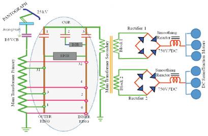
Traction motor is the most important part of any locomotive converting electrical energy into mechanical, requiring sturdiness of electrical, mechanical, magnetic and insulation system for safe and reliable function. In DC series, motors are mostly used, and about 80% of this motors are used in India. DC electric motors usually work under 3KV supply and AC traction motor under 25KVA general circuit of electric locomotive with DC series motor as shown in Figure 1.
Figure 1. General layout of electric locomotive
The mechanics involves conversion of overhead electrical power in rail horse power to haul a train encountering acceleration, train grade, curve resistance and similarly braking. Traction Mechanics involve the concept of train resistance, tractive effort, braking effort, adhesion and balancing speed. The units are followed in day to day talk of Railways which are different when compared to conventional MKS system. Conversion table is shown in Table 1. Figure 2 shows the general electric locomotive with traction motor.
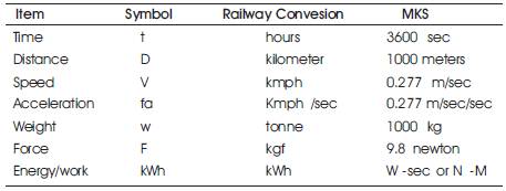
Table 1. Conversion table
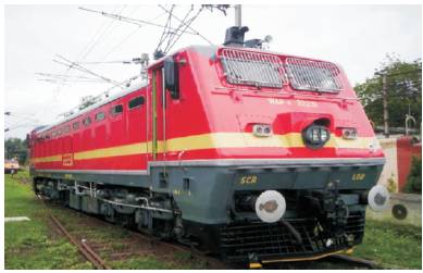
Figure 2. Electric traction locomotive
Torque density is an important index for comparison of traction machines. Consider the basic equation of force on a conductor carrying current I of active length L in a magnetic field B as given,
Force(F) = B*I*L
Torque(T ) = B*I*L*r
Where r is rotor radius,
Current(I) = J*k*r
Where J is the rotor B surface current density, k depends on winding topology and number of poles then,
Torque = B*J*K*L*r2 = B*J*k*Vm
Where Vm is the magnetic volume of rotor and k is constant.
hence
Torque density = B*J*k*
Power is a product of torque and speed for a given torque density. Speed is constrained in DC machine due to commutation, whereas it can go higher in synchronous and induction motor. This improves power density. Higher gear ratio is used to reduce the speed at wheel end. Higher speed calls for designing of suspension arrangement to handle the issue of vibration and bearing lubrication. Traction motors for electrical locomotives are typically coupled to drive gears for each respective axle of the loco motive. The amount of current to the traction motors is controlled so that proper propulsion may be carried out depending upon the loading conditions of the engine [7].
Components of series motor include armature and that same current impressed upon the armature and the series field. The coil in the series field make few turns of large gauge wire to facilitate large amount of current flow. This provides high starting torque, approximately 2 times of rated load torque. Series motor armature are usually lap winding. Lap windings are good for high current, low voltage applications because they have additional parallel paths to flow current [5].
Hence DC series motor is preferred for traction purpose. Figure 3 shows the DC series motor circuit and Figure 4 shows the seibu DC traction motor.
To study features of traction power supply system and the characteristic of the traction load deeply, a simulation traction load for experiment and test is necessary. Generally some equipments are used as simulation traction load in lab, such as incandescent lamp, resistance and reactor, electromotor generator, and so on but here matlab software is used for traction simulation [6].
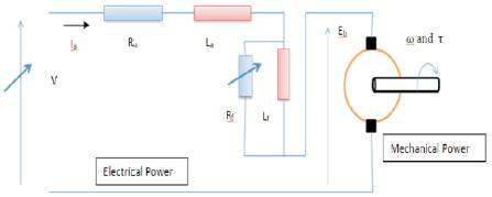
Figure 3. DC Motor with series field
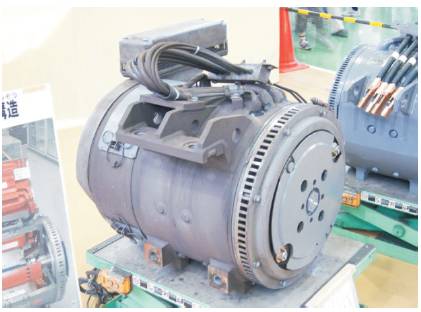
Figure 4. Seibu DC traction motor
DC series motor, with its own characteristics of high starting torque makes it suitable for high inertia as well as traction systems, and has a nonlinear dynamical model. As its name indicates, the field circuit is connected in series with the armature and therefore the armature, and the field currents are the same. The equivalent circuit of a DC series motor is [4]:
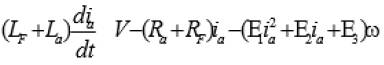
The equation of the armature is
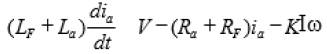
Where Lf : field winding inductance, La : armature winding inductance, ia : armature current, V : applied voltage, Ra : armature winding resistance, Rf : field winding resistance, K : constant depending on the design of the machine, I : flux per pole, equarotational speed of the rotor. The motion equation is
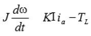
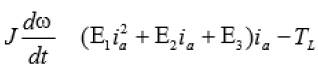
Where J : rotor and load moment of interia and Tl : load torque, Here KI can be expressed in the function of Ia as :
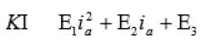
Where E1 = -0.0017, E2 = 0.0938 and E3 = 0.0062. Substituting the values of KI in the above equation, the authors get,
The final equation is,
This equation represents the non linear dynamical behavior of DC series motor including the non linearity of the ferromagnetic material of the machine [4]. Figure 5 shows the Equivalent Circuit of DC Series Motor.
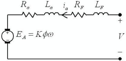
Figure 5. Equivalent Circuit of DC Series Motor
Figure 6 shows the block diagram of single stage control of DC series traction motor. In this single stage control, two traction motors are used from the 25KV AC supply, and it is stepped down for using in the transformer.
The transformer input and output current, voltage are as shown in Figure 7. The input to the rectifier(i.e transformer output) is shown in Figure 8. Rectifier converts AC/DC and gives to the DC series traction motor.
The final output which is the output of the traction motor is shown in Figure 9. The output is from two dc motor but in practical cases for each wheel of locomotive, each motor will be connected.
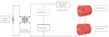
Figure 6. Block diagram of single stage control
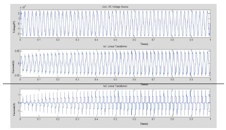
Figure 7. Transformer input and output waveform
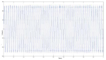
Figure 8. Rectifier Input
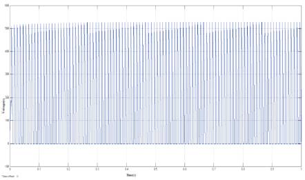
Figure 9. Output Waveform
The block diagram of double stage control of DC traction motor is shown in Figure 10. In this double stage control, four traction motors 25KV is stepped down by using the multi-winding transformer. A multi-winding transformer input and output current is shown in Figure 11. The regulated output is given to each DC motor with snubber and rectifier. Figure 12 shows the rectified Snubber circuit output waveform and Figure 13 shows the Uncompensated output motor control.
Snubber circuit removes the unwanted disturbance, and gives the desired output to the motor, and regulated output voltage is given to each traction motor. The rectified output circuit given to the DC motor and it gives to traction motor is shown in Figure 14 along with the initial condition due to the disturbance oscillations occurred. Now the DC supply is given to each of the traction motor.
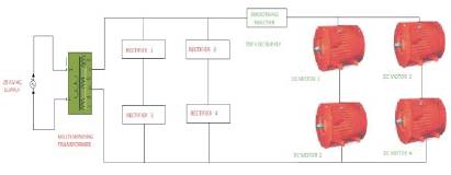
Figure 10. Block Diagram of Double Stage Control
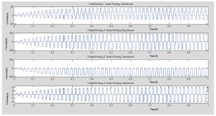
Figure 11. Waveform of Transformer Input and Output Current
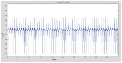
Figure 12. Snubber Circuit Output Waveform
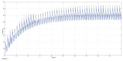
Figure 13. Uncompensated Output Motor Control
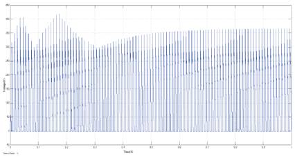
Figure 14. Output of Double Stage Control Waveform
Figure15 shows the comparison of single and double stage control of DC series traction motor. Here initially large disturbance in double stage is compared to a single stage. Because of the control and load after the period of 0.5, it attains stability, but in single stage only it is reliable and in low capacity locomotives.
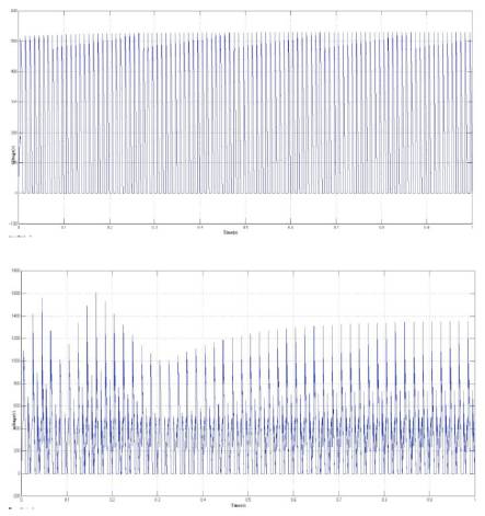
Figure 15. Comparison of Single And Double Stage Control Output
The simulation of single stage and double stage control implementation is proposed and the output characteristics of single stage and double stage are compared as shown in the waveform. In the simulation, DC series motor is used and it is mostly used in railways because it gives excellent speed control, efficiency and also gives the high starting torque with load. Hence the DC series motor is preferable for traction purpose.In double stage control, it needs high cost and used in high capacity locomotive. Here all simulations are done by using MATLAB.