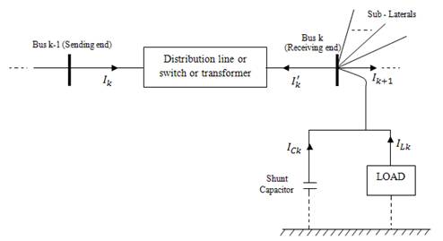
Figure 1. Basic Building Block of Distribution System
Distribution system is the system which supplies electrical power from the generating station to consumers. But the practical loads in the radial distribution systems are generally unbalanced in nature. For analysing the systems condition and also to forecast the load, the study of power flows is essential. The presence of high R/X ratio of the distribution system poses a challenge to the convergence criteria of commercial load flows such as Newton Raphson Method, Gauss Seidel method and Fast Decoupled methods. For this type of systems, some changes have been incorporated in the above methods so as to obtain better convergence which are named as modified Newton Raphson Method, modified Gauss Seidel Method and Forward/Backward Sweep Methods. The pre-assumption of flat node voltage is essential to carry out the load flow solution in all these methods. A new method has been proposed to determine the solution without any preassumptive flat node voltage and also the unbalanced system is modelled as a balanced system using symmetrical components. The solution is obtained by incorporating the relationship between node currents and branch currents using the concept of Branch Incidence matrix and thereby eliminating the need for flat voltage profile. The proposed method has been presented in three sections. In the First section 1, the formation of the branch incidence matrix by modelling of unbalanced Radial Distribution System comprising of transformers, switches, capacitors etc. using symmetrical components is explained. Next, node voltages and power losses are calculated using branch incidence matrix and system parameters. Finally the results obtained are compared with the existing methods. The proposed method is solved for three different unbalanced Radial Distribution Systems such as IEEE 13 node, 19 node and 25 node systems and the results are presented.
Load flow technique is a very important tool for the analysis of power system and used in operational as well as planning stages. Certain applications, particularly in distribution automation and optimization require repeated load flow solutions. As the power distribution networks become more and more complex, there is a higher demand for efficient and reliable system operation. Consequently, the most important system analysis tool, load flow studies, must have the capability to handle various system configurations with adequate accuracy and speed.
N- Number of nodes
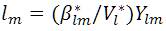
IijA – Branch current flowing through branch ij in phase A
IjA – Current in phase A at node j
VjA - Voltage of phase A at node j
SijA -Complex power flowing from node i to node j in phase ij A
SjA -Specified node power in phase A at node j
ZijA -Impedance of branch ij at phase A
TLijA -Transmission loss of branch ij at phase A
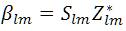
βij - New Variable used in the proposed load flow analysis
K- Branch Incidence Matrix
I-Identity matrix
Null-Null matrix
In many cases, it is observed that the Radial Distribution systems are unbalanced because of single-phase, twophase and three-phase loads [7]. Thus, load flow solution for unbalanced case and hence special treatment is required for solving such networks.
Due to the high R/X ratios and unbalanced operation in distribution systems [18], the Newton-raphson and ordinary Fast Decoupled Load flow methods may provide inaccurate results and may not be converged. Therefore, conventional load flow methods cannot be directly applied to distribution systems. In many cases, the radial distribution systems include un-transposed lines which are unbalanced because of single phase, two phase and three phase loads. Thus load flow analysis of balanced radial distribution systems [1-3] will be ineffective to solve the unbalanced cases and the distribution systems need to be analysed on a three phase basis instead of single phase basis.
In recent days, there has been lot of interest in the area of three phase distribution load flows. A fast decoupled power flow method has been proposed in [4]. This method orders the laterals instead of nodes into layers. Using lateral variables instead of node variables make this method more efficient for a given system topology, but it may add some difficulties if the network topology is changed regularly, which is common in distribution systems because of switching operations. In [5], a method for solving unbalanced radial distribution systems based on the Newton-Raphson method has been proposed. Thukaram et. al. [6] have proposed a method for solving three-phase Radial Distribution networks. This method uses the forward and backward propagation to calculate branch currents and node voltages. A three-phase fast decoupled power flow method has been proposed in [6]. This method uses traditional Newton-Raphson Algorithm in rectangular coordinate system.
In recent days, the Three-Phase Current Injection Method (TCIM) has been proposed [8]. TCIM is based on the current injection equations written in rectangular coordinates and is a full Newton method. As such, it presents quadratic convergence properties and convergence is obtained for all except some extremely illconditioned cases. Further TCIM developments led to the representation of control devices [9-10]. Miu et. al. [11] have also proposed a method for solving three-phase radial distribution networks. However, methods proposed by the researchers reviewed above are complex and high computation time is required.
A fast decoupled G-matrix method for power flow, based on equivalent current injections, has been proposed in [12]. This method uses a constant Jacobian matrix which needs to be inverted only once. However, the Jacobian matrix is formed by omitting the reactance of the distribution lines with the assumption that R>>X; and fails if X>R. In [14], a method has been suggested for three phase power flow analysis in distribution networks by combining the implicit Z-node method [13,19] and the Gauss-Seidel method. This method uses fractional factorization of Y-node matrix. Thus, large computational time is necessary for this method. The Network Topology method uses two matrices, viz. Node Injection to Branch Current (NIBC) and Branch-Current to Node-Voltage (BCNV) matrices, to find out the solution [15]. The Ladder Network theory [16-17] based methods trace the network to and fro from its load end to source end.
In this paper, a new approach is introduced to determine the load flow solution of three-phase radial distribution system which is unbalanced in nature. This method mainly depends on the circuit theory concepts such as incidence matrix which is a branch incidence matrix, which relates the branch currents and node currents at each phase and also a new variable (β) is introduced which relates the node voltages which are connected by the branch at each phase.
The Transmission lines, Transformer and unbalanced loads are modeled by using symmetrical component method.
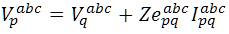
Radial distribution system can be modeled as a network of nodes connected by distribution lines (with or without voltage regulators), switches or transformers. Each node may also have a corresponding load, shunt capacitor and/or co-generator connected to it. This model can be represented by a radial interconnection of copies of the basic building block shown in Figure 1. Since a given branch may be single-phase, two-phase, or three-phase, each of the labeled quantities is respectively a complex scalar, 2x1 and 3x1 complex vector.
Figure 1. Basic Building Block of Distribution System
From the analysis of power transmission line, two fundamental assumptions are made, namely
However, distribution systems do not lend themselves to either of the two assumptions. Because of the dominance of single-phase loads, the assumption of balanced threephase currents is not applicable. Distribution lines are seldom transposed and it cannot be assumed that the conductor configuration is an equilateral triangle. When these two assumptions are invalid, it is necessary to introduce a more accurate method of calculating the line impedance.
A general representation of a distribution system with N conductors can be formulated by resorting to Carson's equations [14], leading to an N×N primitive impedance matrix. For most applications, the primitive impedance matrices containing the self and mutual impedance of each branch needs to be reduced to the same dimension. A convenient representation can be formulated as a 3×3 matrix in the phase frame, consisting of the self and mutual equivalent impedances for the three phases.
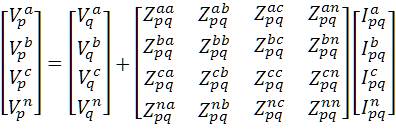
The standard method used to form this matrix is the Kron reduction, based on the Kirchoff's laws. For instance, a four-wire grounded wye overhead distribution line shown in Figure. 2 results in a 4×4 impedance matrix. The corresponding equations are
It can also be viewed in matrix form as
If the neutral is grounded, voltages  and
and  are considered to be equal. In case, from the 1st row of Eqn. 2,
it is possible to obtain
are considered to be equal. In case, from the 1st row of Eqn. 2,
it is possible to obtain
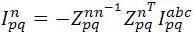
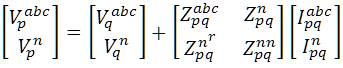
Substituting Eqn. (3) in Eqn. (2), the final form corresponding to the Kron's reduction becomes
whereas,
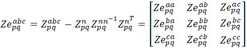
 is the Current vector through the line between nodes
p and q, and can be equal to, the sum of the load currents
of all the nodes beyond the line between node p and q
plus the sum of the charging currents of all the nodes beyond the line between node p and q of each phase.
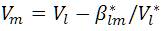
Therefore, the node q voltage can be computed when
the authors know the node p voltage, mathematically, by
rewriting Eqn. (4)
is the Current vector through the line between nodes
p and q, and can be equal to, the sum of the load currents
of all the nodes beyond the line between node p and q
plus the sum of the charging currents of all the nodes beyond the line between node p and q of each phase.
Therefore, the node q voltage can be computed when
the authors know the node p voltage, mathematically, by
rewriting Eqn. (4)
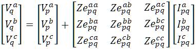
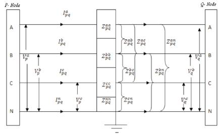
Figure 2. Three-phase Four-Wire Distribution Line
The previous line section model can be improved by the inclusion of line charging representation. The shunt capacitances phase to phase and phase to ground, depicted in Figure 3, can be taken into account through additional current injections.
These current injections for representing line charging, which should be added to the respective compensation current injections at nodes p and q, are given by
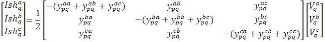
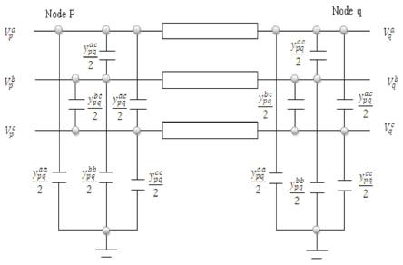
Figure 3. Shunt admittance of line section
In distribution systems, loads can exist in one, two and three phase loads earthier wye or delta is connected. Also loads can be categorized into three types depending upon the load characteristics [23].
Constant power, constant impedance and constant current.
Constant Power: Real and reactive power injections at the node are kept constant. This load corresponds to the traditional PQ approximation in single-phase analysis.
Constant Impedance: These types of loads are useful to model the large industrial loads. The impedance of the load is calculated by the specified real and reactive power at nominal voltage and is kept constant.
Constant Current: The magnitude of the load current is calculated by the specified real and reactive power at nominal voltage and is kept constant.
Table 1. Summarizes the sport load model
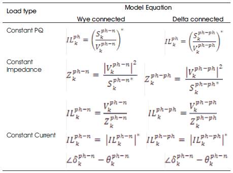
Table 1. Spot Load Model
Sometimes the primary feeder supplies loads through distribution transformers tapped at various locations along line section. If every load point is modeled as a node, then there are a large number of nodes in the system. So these loads are represented as lumped loads
The capacitor is modeled as a constant impedance matrix. The current injection into node k from a capacitor is
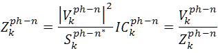
When capacitor bank is wye connected and
When capacitor bank is delta connected.
Switches are modeled as branches with zero impedance.
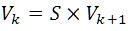
Forward sweep
Backward sweep
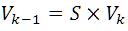
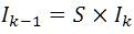
Where S=0 or 1
The impact of the numerous transformers in a distribution
system is significant. Transformers affect system loss, zero
sequence current, grounding method, and protection
strategy. Three-phase transformer is represented by two
blocks shown in Figure. 4, One block represents the per
unit leakage admittance matrix  , and the other block
models represent the core loss as a function of voltage on
the secondary side.
, and the other block
models represent the core loss as a function of voltage on
the secondary side.
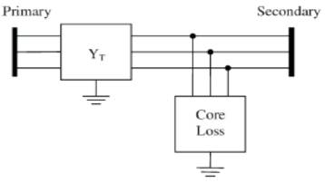
Figure 4. General Three-phase Transformer Model
The unbalanced radial distribution system is modeled (as shown in previous section) and the load flow solution is obtained by using the following steps [20,21]. The results of the load flow are on per phase basis. The matrix K is branch incidence matrix. It is a non singular square matrix of order N-1.The branch incidence matrix is constructed in a simple way like node incidence matrix. In this matrix K, each row is describing the BRANCH incidences. The branches are numbered in conventional way i.e. the no of branch 'lm' is m-1.
K (m, m) =I
K(m, j(m)) = -I
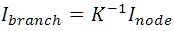
Let consider a Radial Node System which is shown in the Figure 5. Table 2 shows the Element incidence matrix
K (1, 2) =K (1, 5) =-1
Therefore the K-matrix for the above system or network is as follows.
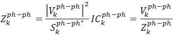
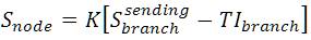
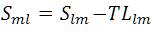
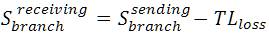
The relationship between the branch currents and node currents can be extended to complex branch powers and node powers[22]. The sending end power and the receiving end powers are not same due to transmission loss. The transmission loss is included as the difference between the sending end and receiving end powers.
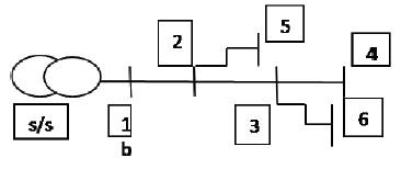
Figure 5. Sample 6 node RDS.
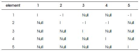
Table 2. Element incidence matrix
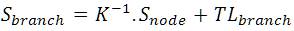
The relationship between branch powers and node powers are established in the same way as per node/branch currents. Multiplying both sides by element incidence matrix K
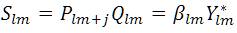
The power flow equations are complex quadratic equations .A new variable Rlm is introduced for each element 'lm' and the equations become recursively linear.
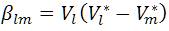
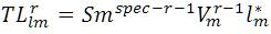
The branch power of 'lm' element is expressed in terms of βlm
The proposed method is summarized as follows
The node currents are determined from Eqn. (2) and then the node powers are calculated. Since the transmission losses are neglected in the first iteration, there will be mismatch between the specified powers and calculated powers. The mismatch is a part of the transmission loss. TLlmr is the transmission loss part for 'lm' element for each element and is the summation of the transmission loss portions of all previous iterations
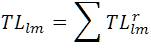
where r is the iteration count
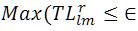
It can be concluded that the power flow solution always exists for a distribution system irrespective of the R/X ratio if it is having connectivity from the source (slack node) to all the nodes. The limitations of the algorithm are being investigated [10] in view of voltage stability limit. For system having less transmission loss, the algorithm will perform faster. The convergence criteria is the 'r' th iteration of the transmission loss part in which each of the element should be less than the tolerance value.
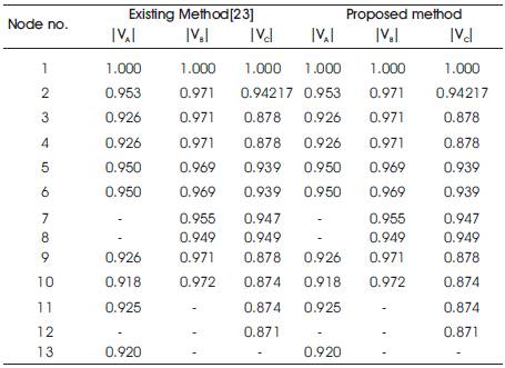
Table 3. Summary of the voltage profiles of IEEE 13 node URDS
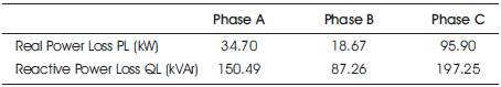
Table 4. Real and reactive power losses of IEEE 13 node at each phase
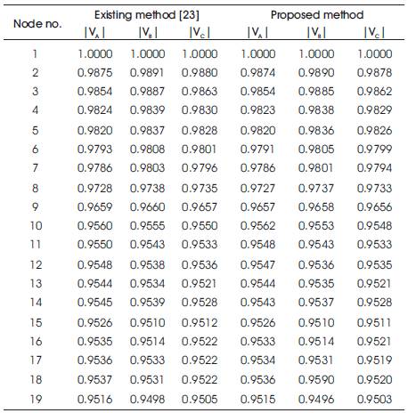
Table 5 Voltage profile of 19 node URDS
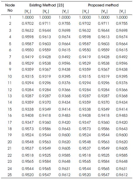
Table 6. Voltage profile of 25 node URDS
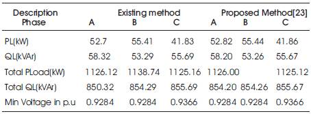
Table 7. Summary of Load Flow Results of 25 node URDS
The proposed algorithm is implemented for 3 different URDS consisting of IEEE 13 node, 19 node and 25 node systems and the results are given in Tables 3, 4, 5,6 and 7.
The voltage profile, real and reactive power losses of IEEE 13 node URDS has been given in Table 3 and Table 4 respectively. It is observed that the total real and reactive power losses are less at phase B when compared to the three phases.