Figure 1. Circuit Model of Matrix Converter
This paper presents a matrix converter for power flow management. The matrix converter has several advantages over traditional rectifier-inverter type power frequency converters. It provides sinusoidal input and output waveforms, with minimal higher order harmonics and no sub harmonics. As the matrix converter is having the ability to generate multilevel output voltages, this converter is able to produce better quality output waveforms than conventional matrix converter in terms of harmonic content. This paper gives the performance of a matrix converter, and the qualitative analysis of some performance parameters are carried out. Some numerical results based on a simulation model of a matrix converter system are also presented. The simulations results of different load conditions are presented. The open loop controlled system is simulated and the waveform output is predicted at various conditions.
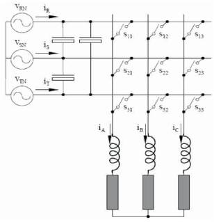
Matrix converters are one-stage converters capable of providing simultaneous voltage and frequency transformation. They can be applied to any multi-phase system, but the most significant case is the 3-phase to 3-phase converter. This consists of nine 4-quadrant or bidirectional switches distributed in a 3x3 matrix form as shown in Figure 1.
Figure 1. Circuit Model of Matrix Converter
These switches connect each input phase with the three output lines. There are no energy storage elements such as large capacitors and inductors. The inductive load and the input filter capacitors filter the high frequency current components produced by the high frequency switch commutations. Despite all of its eye-catching features, matrix converters are not commonly seen in commercial applications. There are several reasons for this rejection [P. W. Wheeler and J. Rodriguez, 2010]. Consequently, electrical motors or any other standard device connected as load to a matrix converter do not operate at their nominal rated voltage.
Despite these drawbacks, there are several reasons why matrix converters remain very attractive for some applications [M. Venturini and A. Alesina, 2010]. Firstly, there are applications where energy storage elements like capacitors and inductors are to be avoided. For example, the large electrolytic capacitor of a dc-link converter is one of the elements that decrease the reliability of the converter. Secondly, the cost of power semiconductors continues to fall and there is no evidence to suggest that this trend will change for the foreseeable future.
The simulation circuit model of a matrix converter is a very attractive solution when regeneration is required. The bidirectional power flow capability and input displacement factor control of matrix converters make them an ideal solution for same application [P. W. Wheeler and J. C. Clare, 2009]. The matrix converter will also benefit from the current trend in electrical drive technology to integrate the frequency converter, the electrical motor and even the gear or pump into a single unit in order to reduce costs and increase overall efficiency and equipment reliability.
By redesigning the loads to operate at lower nominal voltages, the disadvantage of the low output input voltage ratio is overcome. It is relevant to point out once again that the fully controlled line commutated converter can rectify AC to DC between control angle 0 < a < 1800 and can invert DC supply to the AC between the control angle range 900 < a < 2700 , at the line frequency.
The matrix converter consists of several bi-directional switches that allow any output phase to be connected to any input phase. The circuit scheme is shown in Figure 2. The input terminals of the converter are connected to a three phase voltage-fed system, usually the grid, while the output terminal are connected to a three phase current- fed system, like an induction motor might be. The waveform of input voltage is as shown in the Figure 3. Their size is inversely proportional to the matrix converter switching frequency [P. Nielsen, F. Blaabjerg, and J. K. Pedersen, 2011].
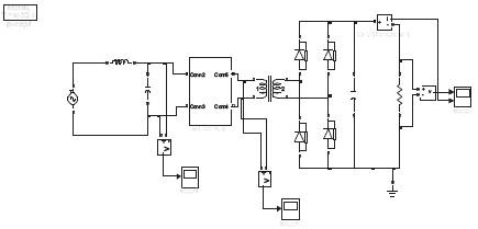
Figure 2. Matrix Converter Circuit Diagram
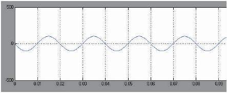
Figure 3. Input Voltage
It is worth noting that due to its inherent bi-directionality and symmetry a dual connection might be also feasible for the matrix converter: a current- fed system at the input and a voltage- fed system at the output. The matrix output at various conditions is as shown in the Figure 4 to Figure 6. The output current waveform is as shown in the Figure 6. But not all of them can be usefully employed. Regardless to the control method used, the choice of the matrix converter switching states combinations (from now on simply matrix converter configurations) to be used must comply with two basic rules. Taking into account that the converter is supplied by a voltage source and usually feeds an inductive load, the input phases should never be short-circuited and the output currents should not be interrupted [J. Mahlein, M. Bruchmann, and M. Braun, 2011]. From a practical point of view these rules imply that one and only one bi-directional switch per output phase must be switched on at any instant. By this constraint, in a three phase to three phase matrix converter 27 are the permitted switching combinations.
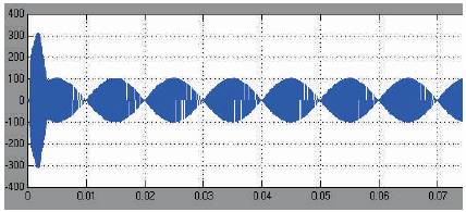
Figure 4. Matrix Converter Output
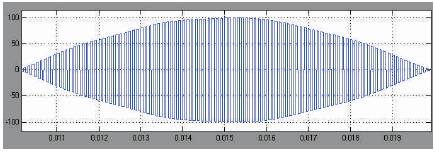
Figure 5. Matrix Converter Output
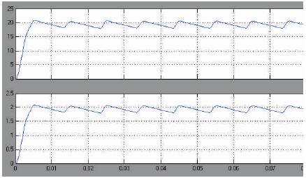
Figure 6. Output Voltage & Current
Since no energy storage components are present between the input and output sides of the matrix converter, the output voltages have to be generated directly from the input voltages [A. Schuster, 2011]. Each output voltage waveform is synthesized by sequential piecewise sampling of the input voltage waveforms. The sampling rate has to be set much higher than both input and output frequencies, and the duration of each sample is controlled in such a way that the average value of the output waveform within each sample period tracks the desired output waveform [R.H. Lasseter and P. Paigi, 2010].
The simulation model of open loop system with disturbance is as shown in Figure 7. The disturbance created in the voltage is that time of 2 sec. The matrix converter can be operated and the voltage is increased at the same time of 2 sec as shown in the Figure 8. It is represented by the Figures 9 and 10 respectively. Likewise to the output voltages, the input currents are directly generated by the output currents, synthesized by sequential piecewise sampling of the output current waveforms. If the switching frequency of the matrix converter is set to a value that is much higher than the input and output frequency, the input currents drawn by the converter are sinusoidal: their harmonic spectrum consists only of the fundamental desired component plus a harmonic content around the switching frequency.
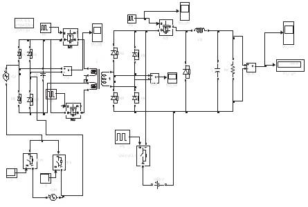
Figure 7. Circuit Diagram for Open Loop with Disturbance
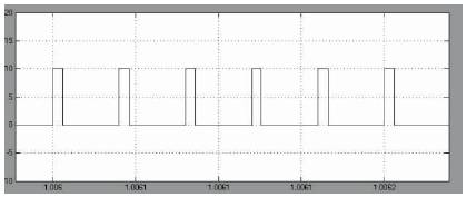
Figure 8. S3 Pulse Waveform
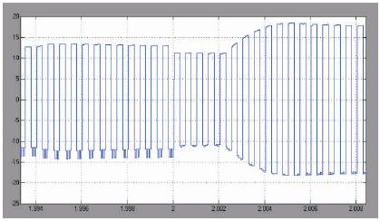
Figure 9. Output Across Transformer Primary Side with Disturbance
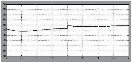
Figure 10. DC Output Waveform with Disturbance
The transformer output is as shown in Figure 11. It can be noted that the amplitude of the switching harmonic components is comparable to the fundamental amplitude. It is then obvious that an input filter is needed in order to reduce the harmonic distortion of the input line current to an acceptable level. The pulse output is as shown in Figure 12. The matrix converter performance in terms of input currents represent a significant improvement with respect to the input currents drawn by a traditional VSI converter with a diode bridge rectifier, whose harmonic spectrum shows a high content of low-order harmonics. By the light of the standards related to power quality and harmonic distortion of the power supply this is a very attractive feature of matrix converter.
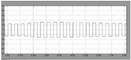
Figure 11. Transformer Output
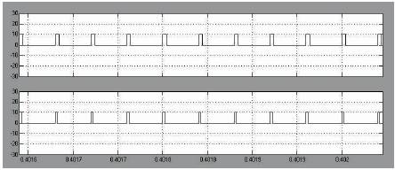
Figure 12. S3, S4 Pulse Output
The modulated output of stabilized voltage is as shown in Figure 13. If the matrix converter is incorporated in the simulation, the signal step response is not affected even when the disturbance is created. The output voltage level is limited to a maximum of 86% of the input. This limit results from the fact that at no time can the output amplitude be larger than the input amplitude, otherwise pulse dropping occurs in the PWM controller. This improvement is better than that can be achieved by merely doubling the carrier frequency as the carrier which remains has lower amplitude.
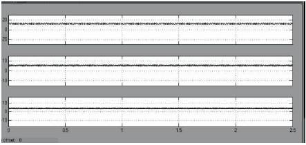
Figure13.12v, 5v, 3.3v Outputs
In order to further increase the attractiveness of matrix converters, it has been integrated into the matrix converter topology to improve the output waveform quality. A single phase digitally controlled switch mode power supply based on matrix converter is analyzed and simulated. The simulation results were found to coincide with the theoretical result. Conventional switch mode power supply system was also simulated. Having the ability to generate multilevel output voltages, the multilevel matrix converter topology is able to generate better quality output waveforms.