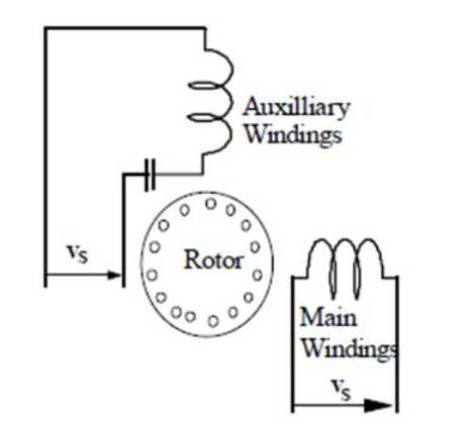
Figure 1. Single Phase Induction motor
Single-phase induction motors are widely used in fractional power applications such as fans, refrigerators and air conditioners. An improvement in its performance means a great saving in electrical energy. The motor can be operated at constant speed or controlled by ON/OFF strategy which results in poor performance and low power factor. An inverter-fed variable frequency motor is a typical example of such improvement. Nowadays, a direct AC-to-AC converter commonly termed as Matrix Converter has a simple structure and many attractive features. These converters have the characteristics such as four quadrant operation, unity input power factor, no dc-link capacitor and high quality voltage/current waveforms. Matrix Converters are replacing the conventional Voltage Source Inverters. In this regard, this paper presents a comprehensive analysis of the performance of the single-phase induction motor when it is fed with single phase inverters and matrix converters. Sinusoidal Pulse Width Modulation (SPWM) technique is used to generate the firing pulses for power switches of the inverter and matrix converter. Simulations were done using MATLAB/Simulink software package and the results were analyzed and presented.
Most of researches for motor drives focused on high power industrial applications which require high performance drive of three-phase induction motors, and that of the Single Phase Induction Motor (SPIM) was out of interest [5].
The advances in domestic and commercial applications in modern life raised the urgent needs to use low power SPIM, so that SPIM became the most widely used type of low power ac motors specially for those applications, where a three phase power is not available [8-10]. Some of these applications need variable speed ac motors which need sophisticated control systems and drive circuits. Traditionally, variable speed operation of a single-phase induction motor is suffering from large harmonic injection into the supply and low power factor, in addition to the limited speed [6].
Nowadays, analysis of induction motors controlled with power converters has been investigated extensively [1-3]. However, most of these studies deal with three-phase induction motors. Although single phase induction motors are usually built with small power, they are widely used in domestic and commercial applications, than three phase induction motors. In fact, the single-phase induction motor is the most commonly used motor used in the utility network. However, the analysis of single-phase induction motors have not received considerable attention in the literature as of yet.
This paper presents a speed control scheme for a single phase induction motor fed with inverters and also with matrix converters. This paper contributes to the analysis of single phase induction motors and is set to examine their performance when fed with controlled inverters and matrix converters.
Single Phase Induction Motors are traditionally used in constant speed home appliances, usually in locations where only single-phase energy supply is available without any type of control strategy. It has the advantages of single phase source to use and simple structure, applying to all kinds of technical fields, especially in home instruments. They are found in air conditioners, washers, dryers, industrial machinery, fans, blowers, vacuum cleaners, and many other applications. These motors are usually used in fixed speed drives [4-7]. But some time variable speed of SPIM is required. Variable speed controls of motors are widely employed in industrial applications because of the obvious energy-saving benefits. The cost reduction and high efficiency of power electronic and microelectronic devices are motivating to implement a SPIM drives in both industrial and domestic applications.
Adjustable speed drives for the three phase induction motors are widely available. This drive cannot be directly applied to single phase induction motor drive. From the last two-three decades there has been an extensive research and development efforts made for a variable-frequency, variable-speed AC machine drive technology and because of that the majority of variable speed drive applications using dc drives previously have been fast replacing by AC drives. In most cases, new applications use AC drives. During recent years, many research laboratories have focused on variable-speed drives, especially for the SPIM, and major improvements have been achieved. The availability of low-cost static converters makes the economic use of energy and improvement of the quality of the electromagnetic torque in SPIM [3-5].
Single-phase induction motors are usually constructed with two windings (main and auxiliary windings) on the stator side and squirrel cage winding in the rotor side. The auxiliary winding is used to produce a rotating field to start the motor. The axis of the auxiliary winding is placed 90 degrees electrical ahead of the main winding as shown in Figure 1.
Figure 1. Single Phase Induction motor
The dynamic simulation of the motor is presented in the stationary d-q frame to facilitate the application of the inverter and later on with the feedback regulators. Since the axes of the main and auxiliary windings are already orthogonal, the stationary d-q axes are chosen that is aligned with the orthogonal axes of the physical windings. The squirrel cage rotor is represented by equivalent two coils transformed to the stationary d-q axis as shown in Figure 2.
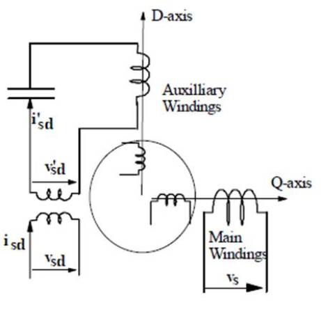
Figure 2. d-q Transformation of SPIM model
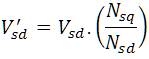
Since the two stator windings, namely the main and auxiliary coils have different number of turns they will yield different mutual reactances. Therefore, a transformation is made to transfer the auxiliary winding to an equivalent winding with the same number of turns as that of the main coil. The new variables referred to the equivalent coil are given in the equations.
The voltage equation of the motor can be written in the d-q stationary frame as follows;
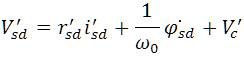
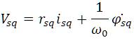
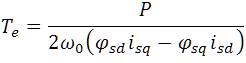
The motor equations are given by
Where 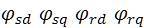 are the d-q stator and rotor flux linkage respectively.
  are the d-q stator resistances, P is the number of poles,
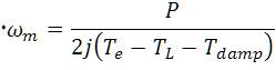
 is the developed torque,
 is the load torque and
  is the damping torque.
An inverter converts a DC input into an AC output statically with the output sinusoidal in nature. However the waveforms of practical inverters are non-sinusoidal and contain certain harmonics. For low and medium power applications, square-wave or quasi-square-wave voltage may be acceptable and for high-power applications, low distorted sinusoidal wave forms are required. With the high-speed power semiconductor devices the harmonic contents of output voltage can be minimized by switching techniques. A single phase inverter system can be depicted as shown in Figure 3. The inverter maybe used to transform a fixed DC voltage input into a variable voltage variable frequency output.
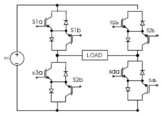
Figure 3. Representation of Single Phase Inverter
An inverter is a circuit which is used to convert DC into AC supply, wherein a matrix converter is an advanced circuit topology for converting AC of fixed voltage and frequency into AC of variable voltage and variable frequency [5-7]. The matrix converter circuit consists of an array of bi-directional switches arranged together, so that any of the output lines of the converter can be connected to any of the input lines. The switches allow any input phase to be connected to any output phase. The output waveform is then created using a suitable modulation pattern similar to a normal inverter, except that the input is a single-phase AC supply instead of a fixed DC voltage. This approach removes the need for the large reactive energy storage components (inductances and capacitances) used in conventional inverter based converters. A single phase matrix converter is shown in Figure 4.
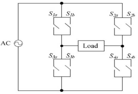
Figure 4. Representation of Single Phase Matrix Converter
The Single-Phase Matrix Converter consists of a matrix of input and output lines with four bidirectional switches connecting the single-phase input to the single-phase output at the intersections. It comprises of pair of four ideal switches Sl, S2, S3 and S4 capable of conducting current in both directions, blocking forward and reverse voltages (symmetrical devices) and switching between states without any delays [2, 5]. The IGBTs are used as power switches due to its popularity to use high power applications with reasonable fast switching frequency for fine control.
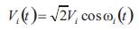
The input voltage of the matrix converter is given by
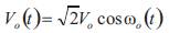
The matrix converter will be designed and controlled in such a manner that the output voltage is given a
The most efficient method of controlling the output voltage is to incorporate PWM control within the converter. Though there are different PWM control techniques, the Sinusoidal Pulse Width Modulation (SPWM) is a well known shaping technique.
The SPWM signal generation is shown in Figure 5. The gating signals are generated by comparing a sinusoidal reference signal Vr with a triangular carrier wave of Vc. The crossover point are used to determine the switching instants of the switches. This particular technique is being used to synthesize the AC output of the SPMC.
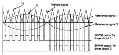
Figure 5. Sinusoidal Pulse Width Modulation
Single phase inverter is modeled using MATLAB/Simulink software. Figure 6. shows the MATLAB/Simulink model of single phase inverter fed single phase induction motor. A carrier wave signal is being compared with the reference sinusoidal signal in order to generate the pulses for the single phase inverter. A PI regulator is being used in order to regulate the voltage before modulating the signal. Sinusoidal Pulse Width Modulation technique is applied to generate the gate drive signals. These gate drive PWM pulses are used to control the output voltage and output current of the inverter.
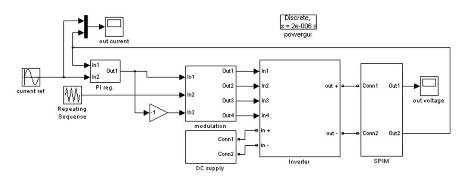
Figure 6. MATLAB/Simulink model of Single Phase Inverter fed SPIM
Figure 7 and 8 shows the MATLAB/Simulink model of matrix converter fed single phase induction motor and matrix converter subsystem. A reference signal is being compared with the carrier wave signal in order to generate the PWM pulses to the matrix converter which drives the motor.
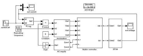
Figure 7. MATLAB/Simulink model of Single Phase Matrix Converter fed SPIM
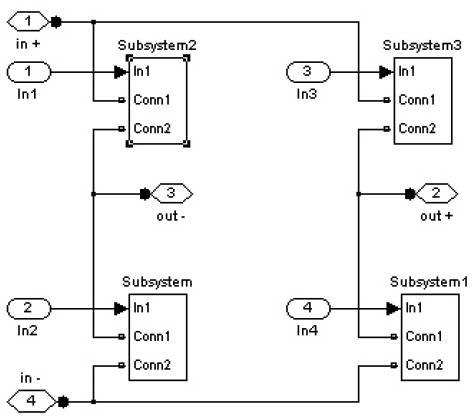
Figure 8. MATLAB/Simulink model of Single Phase Matrix Converter Subsystem
The single phase matrix converter feeding single phase induction motor is simulated to validate the results of the converter performance for various output frequencies. SPWM technique is applied in the simulation to generate drive signals.
Figure 9 shows the switching pulses for the single phase inverters. During the positive half cycle, switches 1 and 4 conducts and during negative half cycle, switches 2 and 3 starts its conduction. It can be seen that, when the switches S1 and S4 are in ON condition, switches S2 and S3 will be in OFF position.
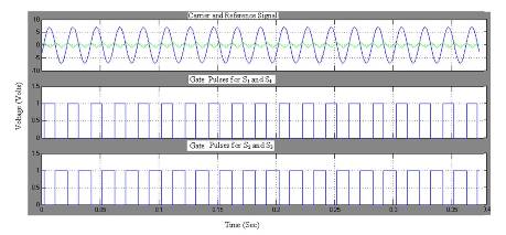
Figure 9. Switching Pulses to Inverter
Figure10. shows output voltage of the inverter, which is being supplied to the induction motor. The magnitude of the output voltage is 230V.
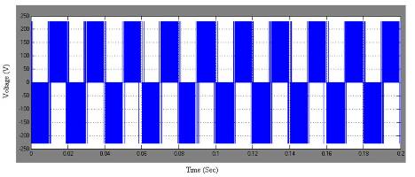
Figure 10. Output Voltage of the Inverter
Figure11 shows the harmonic content of the output voltage of the inverter and value of THD is 42%. The output voltage produced by the inverter is square waveforms which produce more harmonics.
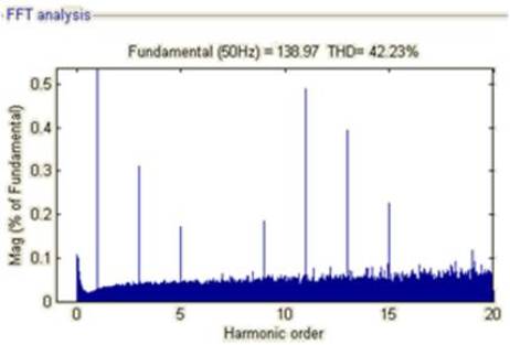
Figure 11. Harmonic Spectrum for Output Voltage of the Inverter
Figure12 shows the output current of inverter. Its amplitude is about 7A, which is sinusoidal in nature.
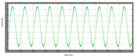
Figure 12. Inverter Output Current
Figure13. shows the main and auxiliary winding currents of single phase induction motors. Auxiliary winding current value is always lesser than that of the main winding current, because the auxiliary windings are being used only at the time of starting. By reducing the motor winding currents, the cost can be reduced.
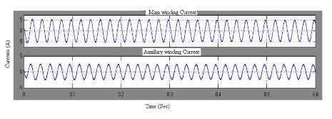
Figure 13. Winding Currents of SPIM fed by Inverter
Figure14 shows the electromagnetic torque of the single phase induction motor. When the speed increases, the torque gets decreases and vice versa.
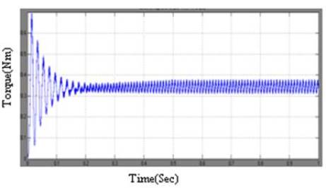
Figure 14. Torque of SPIM fed by Inverter
Figure15 shows the speed of the single phase induction motor fed by the inverter. At the time of starting of motors, the speed increases exponentially and reaches the maximum of about 1500 rpm in 0.5secs.
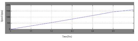
Figure 15. Speed of SPIM fed by Inverter
The Figure 16 shows the input voltage waveform of the single phase inverter and matrix converter at 230V with a frequency of 50Hz.
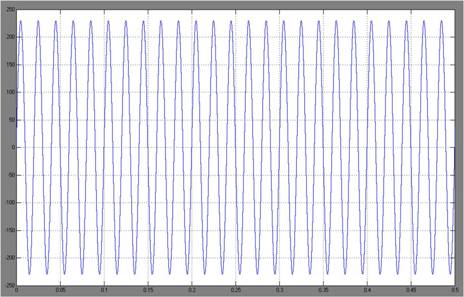
Figure 16. Input Voltage to Matrix Converter
Figure17. shows the input pulses for the single phase matrix converter. During the positive half cycle, switches 1 and 4 conducts and during negative half cycle, switches 2 and 3 starts its conduction.
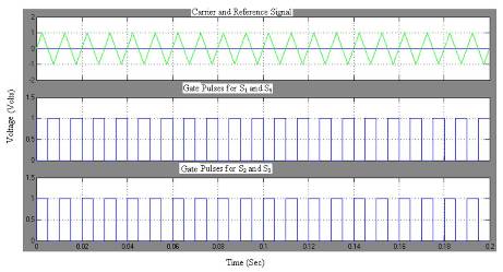
Figure 17. Switching Pulses for Matrix Converter
Figure18. shows the matrix converter output voltage supplied to the induction motor. The output voltage is of pulsed sinusoidal waveform, whose amplitude is about 230V.
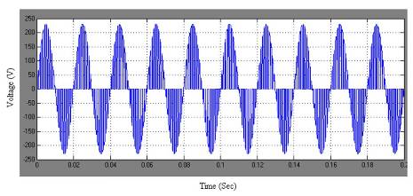
Figure 18. Matrix Converter Output Voltage
Figure19 shows the harmonic content of the output voltage of the matrix converter and value of THD is 15.85%. Because of pulsed sinusoidal waveform of the matrix converter, the harmonics present in the output voltage is less compared to the inverter output voltage.
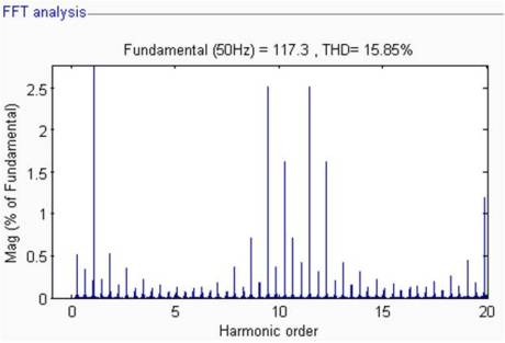
Figure 19. Harmonic Spectrum for Output Voltage of the Matrix Converter
Figure20. shows the output current of matrix converter which is sinusoidal in nature and its amplitude is about 7A. It can be seen that when the output current increases, the harmonic content present in the output also gets increased.
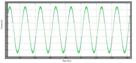
Figure 20. Matrix Converter Output Current
Figure21. shows the stator winding currents of the induction motor, where the main winding current is always higher than that of the auxiliary winding currents, in which the auxiliary windings are being used only at the time of starting.
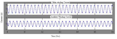
Figure 21. Winding Currents of SPIM fed by Matrix Converter
Figure 22. shows the electromagnetic torque variations with respect to time. It can be seen that by using matrix converters, the torque ripples gets minimized.
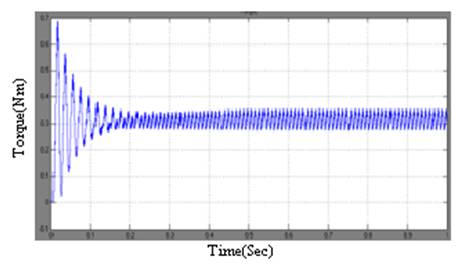
Figure 22. Torque of SPIM fed by Matrix Converter
Figure 23. shows the speed of the induction motor with respect to time. During the starting of motors, the speed may increases exponentially from 0rpm to a maximum of about 700 rpm.
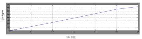
Figure 23. Speed of SPIM fed by Matrix Converter
In this paper, a topology of single phase inverters and single phase Matrix Converters fed single phase induction motor has been simulated and the results were shown. Further, the operation of pulses for the inverters and matrix converters using square wave pulse width modulations has been discussed. Hence, this paper attempts to give an overview of matrix converters, thereby providing an insight into one of the emerging trends of Power Converters. The simulation results are helpful to study the operation of a matrix converter, as an Unrestricted Frequency Changer. Further studies aims to analyze the operation of a matrix converter and inverters for different loading conditions and synthesizes the output voltage using various other modulation techniques.