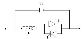
Figure 1. The basic scheme of TCSC
This paper proposes that is a combination of Fuzzy Logic Power Oscillations Damping (FLPOD) controller with Proportional and Integral Power Flow (PIPF) controller for Thyristor Controlled Series Capacitor (TCSC) to enhance the power system stability of multi machine power system. The proposed controller improves the performance of TCSC to effectively damp the power system oscillations after clearing fault in the power system. The TCSC with proposed controller is tested on Western System Coordinating Council (WSCC) – 9 Bus system through simulation by using SIMULINK.
The major problem in the power system is oscillations due to faults and sudden load disturbances. After inventing the Flexible AC Transmission Systems (FACTS) devices power system became more flexible to control. The research work is still going on to invent the new methods for better control techniques using FACTS devices.
TCSC is one of the most popular and powerful series compensation FACTS device [6]. Normally TCSC is used for power flow control [4] in transmission lines and also used to damp the power system oscillations [1] [2] [3]. Because of slow response of PIPF controller, TCSC is not in a position to effectively damp the power system oscillations [3]. It needs some auxiliary signal to improve the performance of TCSC to damp the power system oscillations. In this paper FLPOD controller along with PIPF controller is proposed to achieve this.
Dheeman Chatterjee and Arindam Ghosh [1] have proposed PI controller for TCSC to improve the transient stability. John J. Paserba, Nicholas W. Miller, Einar V. Larsen and Richard J. Piwko [2] have presented a model for TCSC which is applicable for transient and oscillatory studies. Alberto D. Del Rosso, Claudio A. Cañizares and Victor M. Doña [3] have proposed a linear controller for enhancement of stability. Jose H. Vivas and Julie D. Zambrano[4] have described the development of a control system based on PQ theory (Instantaneous power) for TCSC. B.V. Sanker Ram, D.Naga Raju and G.Tulasi Ram Das[5] have proposed PI Power Flow controller.
In the present paper FLPOD along with PI Power Flow controller is designed to enhance the multi machine power system transient stability for damping of power system oscillations.
TCSC is a series compensation device of the FACTS family using power electronics to control power flow in transmission lines and improve transient stability in power system. TCSC controls the power flow in transmission lines by varying the impedance of TCSC by controlling the delay angle of thyristor valves. The basic scheme of TCSC is shown in Figure 1. It consists of the series controlled capacitor shunted by a Thyristor Controlled Reactor (TCR).
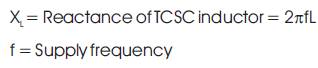
Figure 2 shows the impedance (XTCSC) of TCSC for different values of delay angle (α) of thyristor valves. The TCSC has two operating ranges around its internal circuit resonance (αr): One is the αClim ≤ α ≤ 180o Where XTCSC (α) is capacitive, and the other is the 90o ≤ α ≤ αLlim where XTCSC(α) is inductive. The internal circuit resonance depends on the ratio between Inductor and Capacitor reactance of TCSC. Different ratios of reactance yield different resonance points (αr)[5] .
Figure 1. The basic scheme of TCSC
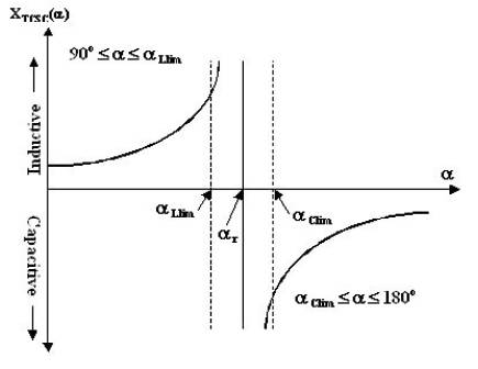
Figure 2. XTCSC vs. characteristic of TCSC
TCSC can operate in three modes. They are
(I) Thyristor blocked (no gating and zero thyristor conduction) shown in Figure 3(a).
(ii) Thyristor bypassed (continuous gating and full thyristor conduction) shown in Figure 3(b).
(iii) Vernier operation with phase control of gating signals shown in Figures 3( c) and 3(d).
In case of blocked operating mode, the TCSC net impedance is just capacitive reactance. In case of bypass mode, as the thyristors are fully conducting, most of the line current flows through thyristors and hence TCSC has small net inductive reactance.
In Verinier control, thyristors are conducted in such a manner that a controlled amount of inductive current can circulate through the capacitor thereby increasing effective capacitive/inductive reactance of the module.
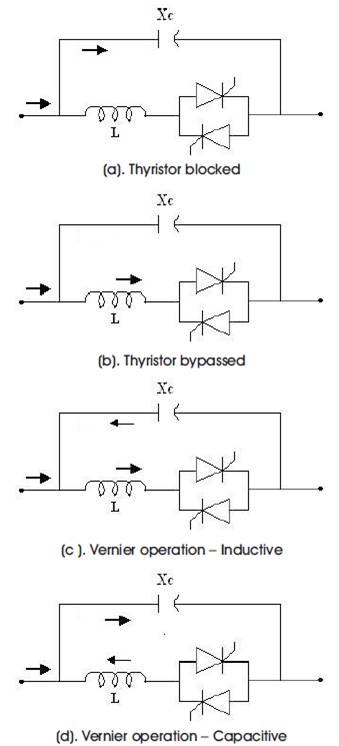
Figure 3. Modes of TCSC operations
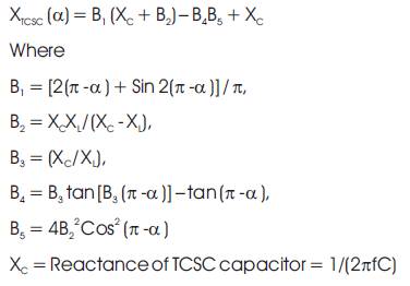
The basic scheme of TCSC is shown in Figure 1. The overall reactance of the TCSC is given in terms of delay angle (α) as [1]
The control offered by TCSC is an Impedance type control that is the inserted voltage is proportional to line current.
The SIMULINK model block diagram for PIPF controller of TCSC is shown in Figure 4.
The SIMULINK model block diagram for combined FLPOD controller with PIPF controller of TCSC is shown in Figure 5. FLPOD controller is fed by one input that is change in power or difference in power (DP). This gives the appropriate reactance (Xe), which is required to the system.
The rules for the proposed FLPOD controller are:
I) If 'DP' is 'DPN' (Change in power Negative) Then 'Xe' is 'XN' (Reactance Negative)
ii) If 'DP' is 'DPZ' (Change in power Zero) Then 'Xe' is 'XZ' (Reactance Zero)
iii) If 'DP' is 'DPP' (Change in power Positive) Then 'Xe' is 'XP' (Reactance Positive)
The membership functions for input and output of FLPOD controller, Change in power (DP) and reactance (Xe) are given in Figure 6(a) and 6(b).
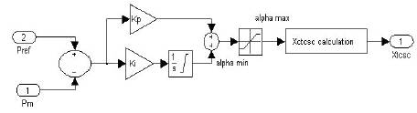
Figure 4. PIPF Controller of TCSC Block Diagram

Figure 5. Combined FLPOD Controller with PIPF Controller of TCSC Block Diagram
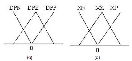
Figure 6. (a) Input membership function (DP) and (b) Output membership function (Xe) of FLPOD controller
Three Machine Nine bus system (WSCC 9 – Bus) [7] is considered with loads assumed to be represented by constant impedance model and all the three machines are operate with constant mechanical power input and with constant excitation as shown in Figure 7. TCSC is placed in 7 – 5 transmission line by the Extended Voltage Phasors approach (EVPA) [5].
The WSCC 9 –Bus system with TCSC placed in 7 –5 Transmission line is simulated in SIMULINK. Figures 8–18 show the results pertaining to the WSCC 9 – bus system with TCSC (equipped with PIPF controller and proposed controller) and without TCSC, when 3-Ph short circuit selfclearing fault occurs at bus – 7 initially (at 0 sec) and fault cleared at 0.1 sec.
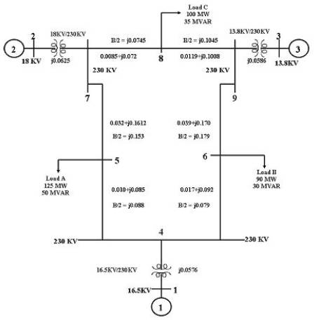
Figure 7. WSCC 9 – Bus system
Figures 8 and 9 are the rotor angle oscillations of generators 2 and 3 with respect to Generator 1. This show TCSC with proposed controller gives better performance when compared to TCSC with PIPF controller. Rotor angle oscillations are effectively reduced with TCSC with combined PIPF and FLPOD controller. Figures 10 – 12 shows the power oscillations of three generators. Figures 13– 15 show the speed (rad/sec) of the three generators. Figures 16 and 17 show variation of voltage at Bus – 5 and 7. Figure 18 shows the reactance of TCSC. From the results shown in Figures 8–18 it can be observed that the TCSC with proposed controller shows better performance.
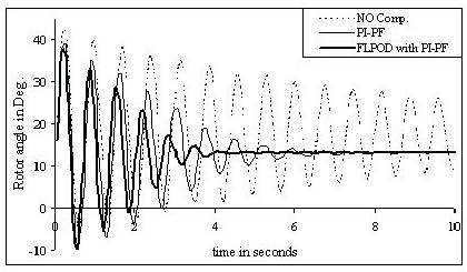
Figure 8. Rotor angle Oscillations of Generator 2 with respect to Generator 1 for 3-Ph Short circuit at bus – 7
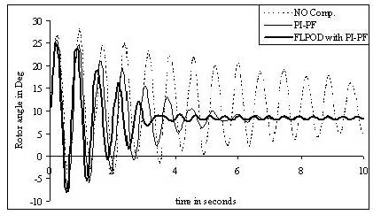
Figure 9. Rotor angle Oscillations of Generator 3 with respect to Generator 1 for 3-Ph Short circuit at bus – 7
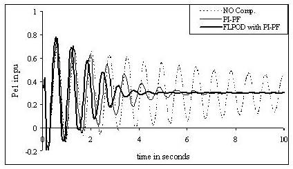
Figure 10. Oscillations in Power output of Generator 1 for 3-Ph Short circuit at Bus – 7
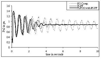
Figure 11. Oscillations in Power output of Generator 2 for 3-Ph Short circuit at Bus – 7
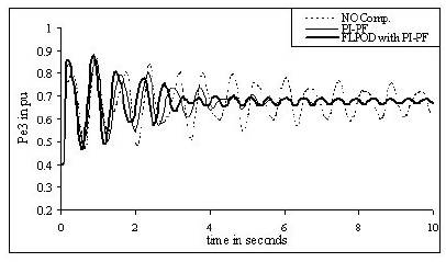
Figure 12. Oscillations in Power output of Generator 3 for 3-Ph Short circuit at Bus – 7
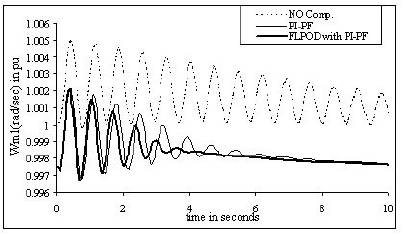
Figure 13. Speed Variation of Generator 1 for 3-Ph Short circuit at Bus – 7
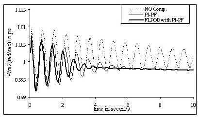
Figure 14. Speed Variation of Generator 2 for 3-Ph Short circuit at Bus – 7
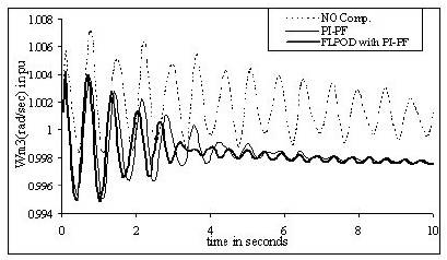
Figure 15. Speed Variation of Generator 3 for 3-Ph Short circuit at Bus – 7
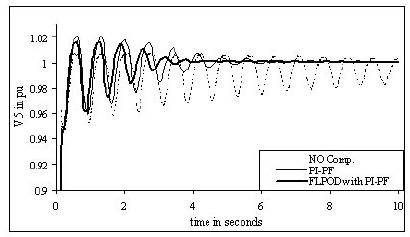
Figure 16 Voltage at Bus – 5 for 3-Ph Short-circuit at Bus – 7
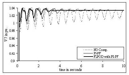
Figure 17 Voltage at Bus – 7 for 3-Ph Short-circuit at Bus – 7
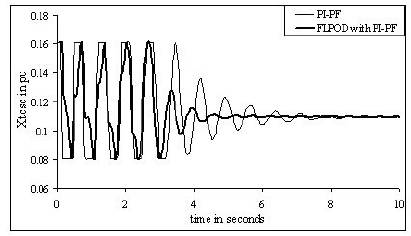
Figure 18 Reactance of TCSC for 3-Ph Short-circuit at Bus – 7
A combined FLPOD controller with PIPF controller for TCSC has been proposed instead of conventional PIPF controller. By observing the simulated results shown from Figures 8 – 18 it can be concluded that the proposed controller shows better performance to damp the rotor angle oscillations and power oscillations under 3 – ph short circuit self cleared fault. In this method locally measured variables are used therefore there is no need for telecommunication link from the generators.
The authors would like to express their sincere thanks to the Department of Electrical and Electronics Engineering, JNTUH College of Engineering, Hyderabad for the facilities extended for completion of this work.
PI PF controller parameters: Kp = 0.8, Ki = 10
FLPOD controller parameters: K = 0.5
TCSC: C = 103.82µ F, L = 6.777mH, PRef = 100MW