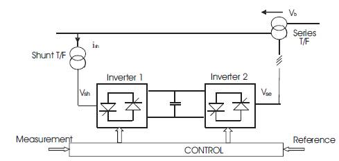
Figure 1. UPFC Installed in Transmission Line
UPFC consists of a parallel and series branches, each one containing a transformer, power-electric converter with turn-off capable semiconductor devices and DC circuit. Inverter 2 is connected in series with the transmission line by series transformer. The real and reactive power in the transmission line can be quickly regulated by changing the magnitude (Vb ) and phase angle (δb ) of the injected voltage produced by inverter 2. The basic function of inverter 1 is to supply the real power demanded by inverter 2 through the common DC link. Inverter 1 can also generate or absorb controllable power [5], [6].
Literature [1] to [10] does not deal with the matlab simulation of UPFC using shunt and series sources. An attempt is made in the present work to model and simulate UPFC using matlab.
2. Simulation Results
Two bus system without compensation circuit is shown in Figure 2a. Sag is produced when an additional load is added. Voltage across loads 1 and 2 are shown in Figure 2b. The real power and reactive power waveforms are shown in Figures 2c and 2d respectively
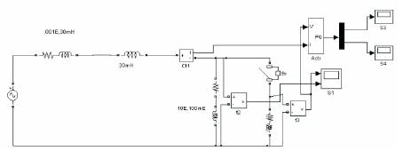
Figure 2a. Line model without compensation
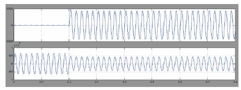
Figure 2b. Voltage across Load -2 and Load -1
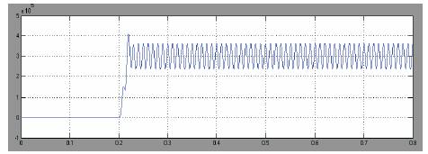
Figure 2c. Real power
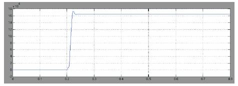
Figure 2d. Reactive power
Two bus system with UPFC is shown in Figure 3a. UPFC is represented as a subsystem. The details of subsystem are shown in Figure 3b. Voltage across loads 1 and 2 are shown in Figure 3c. Real and reactive powers are shown in Figures 3d and 3e respectively. UPFC using voltage and current sources are shown in Figure 4a. Converter 1 is represented as a shunt current source and converter 2 is represented as a series voltage source. Load voltage and current waveforms are shown in Figure 4b. Real and reactive powers are shown in Figure 4c. Variation of powers with the variation in the angle is given in Table 1. The real and reactive powers increase with the increase in the angle of voltage injection.
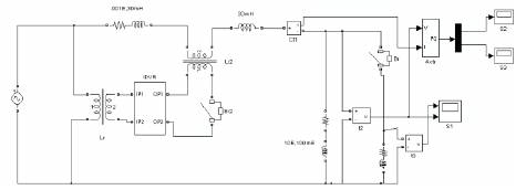
Figure 3a. Two bus system with UPFC
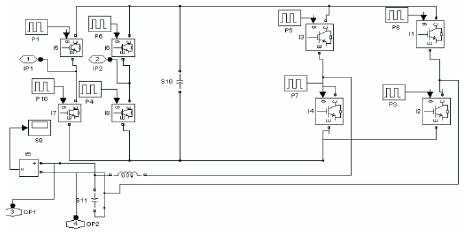
Figure 3b. Rectifier Inverter system
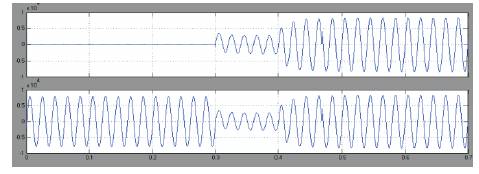
Figure 3c. Voltage across Load 2 and Load 1
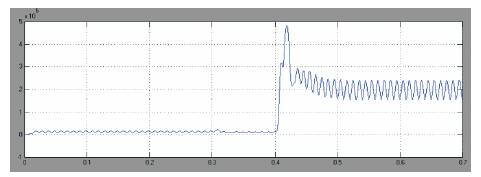
Figure 3d. Real power
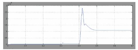
Figure 3e. Reactive power
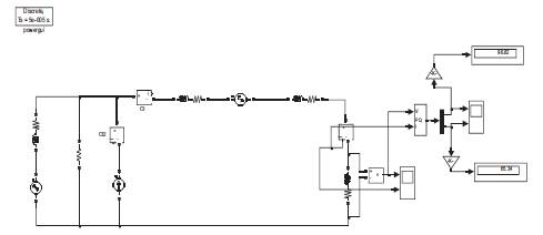
Figure 4a. UPFC circuit model using shunt and series sources
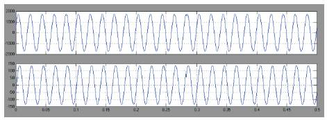
Figure 4b. Load voltage and current waveforms
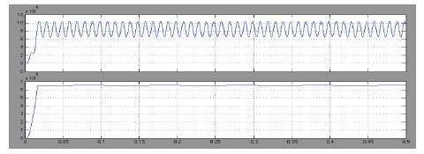
Figure 4c. Real and Reactive power
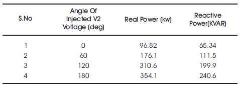
Table 1. Variation of power with angle of injection
Conclusion
In the simulation study, matlab simulink enviroment is used to simulate the model of UPFC connected to a 3 phase system. This paper presents the control & performance of the UPFC used for power quality improvement. Voltage compensation using UPFC is studied. The voltage compensation using UPFC system is also studied by using shunt and series source model. The real and reactive powers increase with the increase in angle of injection. Simulation results show the effectiveness of UPFC to control the real and reactive powers. It is found that there is an improvement in the real and reactive powers through the transmission line when UPFC is introduced. The UPFC system has the advantages like reduced maintanance and ability to control real and reactive powers.