Abstract
India is the world's top producer of two-wheelers, which are frequently used in our daily lives. However, after a few years of service, the engine loses its efficiency and can no longer meet the environmental protection regulations. If these scooters could be transformed into electronic scooters, they could be used for a longer period of time. In this paper, an ordinary two-wheeled Honda Activa Scooter model powered by a two-stroke gasoline engine was converted into an electric vehicle. To increase efficiency, a novel approach known as regenerative braking was implemented. Regenerative braking temporarily conserves kinetic energy during deceleration and then uses it again as kinetic energy, thereby reducing fossil fuel consumption. When braking, a large amount of energy is typically lost as heat, but the regenerative braking system recovers this energy. With this system, the electric motor uses the vehicle's momentum to recover the energy lost while braking.
Keywords:
- Electric Vehicle
- Regenerative Braking
- Kinetic Energy
- Efficiency
- Energy Lost
Introduction
Electric Vehicles (EVs) are becoming the preferred mode of transportation due to rising oil prices and increasing concerns about air pollution and its impact on the environment. However, battery-powered EVs have some challenges, such as limited driving range, insufficient charging and recharging cycles. Regenerative braking is one technique used to address these challenges. When a vehicle decelerates, some of its kinetic energy is converted into electrical energy and stored in the battery (Khande et al., 2020; Malode & Adware, 2016). This process is known as regenerative braking. However, regenerative braking is sometimes ineffective on smooth surfaces and when vehicles need to brake on hills or in. pits. Therefore, mechanical brakes are still necessary in EVs, even though they waste energy by converting the electric energy derived from the EV's kinetic energy. Simple-to-control motors provide regeneration capacity, capturing and storing the kinetic energy lost during braking. When mechanical brakes are used to stop or slow down the vehicle, all the kinetic energy stored in the two-wheeler EVs at the time of braking is lost. Therefore, batteries can be used to capture and store this kinetic energy, increasing the efficiency of EVs.
1. Literature Review
Cheng (2009) provides an overview of the recent work on electric vehicles. The paper describes the development and comparison of different components. The major components in battery technology, charger design, motor, steering, and braking are examined. The research finally shows some electric vehicle prototypes.
Hazari et al. (2014) uses a simple Brushless Direct Current (BLDC) motor control algorithm for low-cost motor drive applications using general-purpose microcontrollers. The proposed design will allow the user to rotate the motor in either a clockwise or anticlockwise direction. Depending on the rotor position, the sensor will give a response to the controller circuit.
Lee et al. (2017) provide an optimal design of an in-wheel motor for an electric scooter (E-scooter) considering economical production. The preliminary development of an in-wheel electric motor which has a direct-driven outer rotor type is attached to the E-scooter's rear wheel without any gearing. The objective of the optimal design of this in wheel motor is to improve the output characteristics of the motor and have a stator form that facilitates automatic winding.
Hazarathaiah et al. (2019) is to design and fabricate a two-wheeled hybrid electric vehicle powered by both batteries and gasoline. The combination of both makes the vehicle dynamic in nature. It provides its owner with advantages in fuel economy and environmental impact over conventional automobiles. Hybrid electric vehicles combine an electric wheel hub motor, battery, and control system with an internal combustion engine to achieve better fuel economy and reduce toxic emissions.
2. Objectives
The design and development of Electric Vehicles (EVs) is driven by several primary goals, including reducing vehicle maintenance costs, decreasing pollutants, and improving the longevity and effectiveness of current EVs. One of the key goals of EV design is to reduce vehicle maintenance costs. EVs have fewer moving parts than traditional internal combustion engine vehicles, which reduces the need for costly maintenance and repairs. Additionally, the use of regenerative braking and other energy-saving technologies can help extend the life of the vehicle's battery and reduces the need for expensive replacements. Another important goal of EV design is to decrease pollutants. EVs produces significantly fewer emissions than traditional vehicles, making them an attractive option for those concerned about air quality and the environment. In addition to reducing emissions during operation, EVs can also be charged with renewable energy sources, further reducing their carbon footprint.
The problems in EVs can include range anxiety, limited charging infrastructure, and high upfront costs. To address these issues, designers and developers are working on improving battery technology, developing more efficient charging systems, and reducing the overall cost of EVs. Finally, increasing the longevity and effectiveness of current EVs is an ongoing goal which includes improving battery performance, developing better charging technologies, and exploring new materials and manufacturing processes that can help extend the life of the vehicle.
3. Block Diagram for Electric Vehicle
The block diagram for an Electric Vehicle (EV) consists of several key components that work together to power the vehicle. The heart of the system is the battery, which provides power to the electric motor. The motor is controlled by an electronic motor controller. Other key components of the EV block diagram includes the power electronics, which convert the battery's DC voltage into the AC voltage needed to power the motor, and the onboard charger, which is used to recharge the battery from an external power source. The charging system may also include a DC-to-DC converter to step down the voltage of the external power source, as well as a charging port and control unit to manage the charging process. Figure 1 shows the main parts of an electric vehicle.
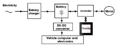
Figure 1. Main Parts of Electric Vehicle.
The majority of the energy in an electric vehicle is stored in the battery, which is charged by the battery charger that adjusts the mains power. The Direct Current (DC) battery voltage is then transformed into a switched-mode signal that drives the motor using a power electronic controller (Cheng, 2009).
3.1 Components in Electric Vehicle
The key components of an electric vehicle include the BLDC hub motor, battery, controller, throttle, DC-DC buck converter, and battery charger.
3.1.1 BLDC Hub Motor
The motor uses the source of electricity to transform it into mechanical energy, and among various motor types, the Brushless Direct Current (BLDC) Motor stands out due to its high efficiency and controllability (Hazari et al., 2014). It offers advantages for power conservation compared to other motor types. The hub motor's operating system is an electronic phase changer (switching circuit) that regulates the energizing of the stator winding to create a spinning magnetic field, which causes the rotor to rotate in response to the position sensor input.
3.1.2 Lithium-Ion Battery
Electrochemical devices, such as batteries, are used to store chemical energy and transform it into electrical energy. In the group of portable battery types, lithium-ion batteries are widely used, where lithium ions move both ways from the positive electrode to the negative electrode after depletion. Some portable lithium-ion (Liion) batteries are used in electronics and electric scooters, making them a popular rechargeable battery option. They have a higher energy density compared to standard nickel-cadmium or lead-acid rechargeable batteries.
3.1.3 Controller Techniques
The device's display, throttle, motor, battery, and other sensors are connected to it. E-bike controllers serve as the brain of your E-bike, controlling every aspect of its operation (Boisvert & Micheau, 2015). Figure 2 depicts the basic block diagram for closed-loop control.
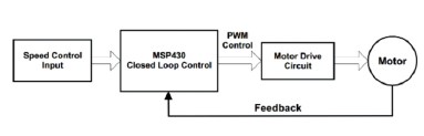
Figure 2. Basic Block Diagram for Closed-Loop Control.
A three-phase motor is controlled using the MSP430, and the loop is closed to create closed-loop control. A Programming Interface (PI) controller is used to implement closed-loop control. Modifications to the timer's Pulse Width Modulation (PWM) duty cycle affect how the motor speed is controlled by the input from the speed control and the feedback from the actual speed of the motor (Xie et al., 2010). An MSP430-based implementation of closed-loop control is shown in Figure 3.
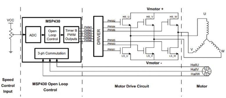
Figure 3. Closed-Loop Control-MSP430 Based Implementation.
The commutation of the 3-phase motor is controlled by the MSP430's PWM outputs, and the duty cycle is used to regulate the current flowing through the motor windings and electrically powered field-effect transistors, thus controlling the motor speed (Hazarathaiah et al., 2019). The Hall sensors attached to the motor provide information about its position to the MSP430, which utilizes them to complete the commutation cycle. General Purpose Input/Output (GPIO) input pins are linked to the hall sensor signals through helpful interrupts. Whenever a hall sensor state change event is detected, the PWM outputs of the motor-drive circuit are updated according to the commutation sequence.
In an e-twist bike, the throttle is activated by rotating the handlebar's end towards the rider. The throttle is a crucial component in electric vehicles with regenerative braking systems, as it controls the power delivered to the electric motor. The throttle regulates the motor speed and the amount of torque generated. Typically, in an electric vehicle, the throttle is an electronic control unit that sends signals to the motor controller to adjust the power delivered to the motor. The regenerative braking system utilizes the motor as a generator to convert the vehicle's kinetic energy into electrical energy during deceleration. The throttle plays an essential role in regulating the regenerative braking system, ensuring that the generated energy is captured and stored in the vehicle's battery for future use.
3.1.5 Buck Converter, DC-DC
A step-down DC-to-DC converter that is used to convert a fixed DC input voltage to a predetermined DC output voltage is called a Buck Converter. The output voltage of a buck converter is never allowed to exceed the input voltage. It steps down the voltage of the input DC power source to a lower voltage that is suitable for the electric motor and other components of the vehicle. Figure 4 shows the basic buck DC-to-DC converter.
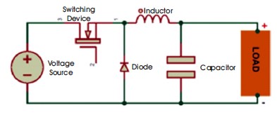
Figure 4. Basic Buck DC-DC Converter.
This is achieved by using a switching transistor and an inductor to convert the DC voltage into a pulsed waveform. The average voltage of the pulsed waveform is lower than the input voltage, allowing efficient power conversion. In an electric vehicle with regenerative braking, the buck converter is used to convert the high voltage generated by the regenerative braking system into a voltage that can be stored in the vehicle's battery for later use
3.1.6 Battery Charger
To increase the battery's capacity, a battery charger must be used. The distinguishing features of a battery charger include weight and price, power density, charging time, weight and price of the charger power density, charging time, efficiency, and dependability. It converts AC electricity into DC while retaining a high-power factor and is known as a power factor-correcting AC-to-DC converter. The charger can be bidirectional, in which case it can feed any surplus power generated by the battery to the electrical system as it charges the battery from the power system, or unidirectional, in which case it can only use the power source to recharge the EV battery
4. Electric Vehicle Working Procedure
Inside each wheel hub is a hub-drive motor. It is typically mounted on the rear wheel of electric bicycles. The stator and hub motor are linked by a gear reduction mechanism. Gearing is required because engines like to turn swiftly, much more quickly than your bike's wheels can. With each spin, the internal gear rotates many times more quickly than its case.
This allows the engine to run at a faster and more efficient speed while still allowing the wheels to rotate at a relatively slow rate. The crucial point is that the hub's gearing lowers the wheel's fast rotation so that it can turn at a more acceptable speed.
Inside the hub motor is the stator, which is made up of several copper windings twined around the spokes. The current from the battery is directed to the cables by the motor controller, which turns the stator into an electromagnet. The rotor is composed of a ring of permanent magnets that generate torque, while the stator's electromagnets rotate the blades. More torque produces better acceleration.
5. Regenerative Brake Technology
Using the technique of transforming energy from motion into a form that can be used instantly or stored for later use, Regenerative Braking (RB) technology slows down moving objects or automobiles (Nian et al., 2014).
5.1 Operating Principles
A type of brake known as regenerative braking uses the mechanical energy of the motor to convert motion into electrical energy, which then flows back to the battery. When the motor turns on, regenerative braking causes the vehicle to slow down as it descends a hill. The motor starts to turn the other way when the brakes are pressed, and the automobile slows down in the incorrect direction (Xiao et al., 2012). When moving in the incorrect direction, the motor serves as a generator and recharges the battery. Figure 5 illustrates the normal driving condition of the motor vehicle.
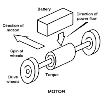
Figure 5. Normal Driving Condition.
Regenerative braking lowers the cost of fuel for electric vehicles, improves the fuel financial system, and reduces emissions. As electric vehicles don't need to decelerate as much when traffic stops and starts, the regenerative braking system provides the braking power when the vehicle's speed is low. Figure 6 shows the braking action with regenerative braking.
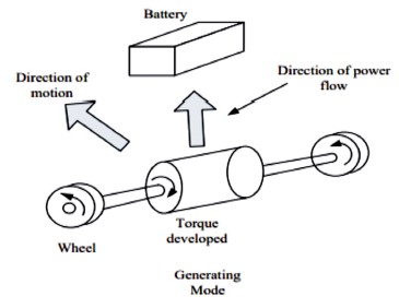
Figure 6. Normal Driving Condition.
These brakes function well when operating a vehicle in an urban environment and stopping in cities. The brake controller monitors the wheel speed and calculates the torque, electricity that will be created, and rotational force that will be fed to the batteries. It also regulates every component of the motorized vehicle, providing a sense of structure to the controller and braking system (Chen et al., 2011). The brake controller controls and directs the motor's electrical output, which is applied to the batteries, and the brakes are used (Yoong et al., 2010).
5.2 Theoretical Calculations
Motor Specification:
Voltage (V) = 48 V
Power (P) = 1000 W
Equation for Power P= IxV
Hence,
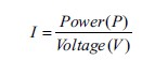

=20.384 Amp
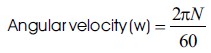
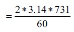
5.2.1 Motor RPM Speed
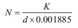
= 731 RPM
where,
N = the rate of revolution
35 km/h is the speed in kmph, and wheel is K
1 inch is equivalent to 2.54 cm, or 10 inches, or 25.4 cm
5.2.2 Motor Torque
=13.06 Nm
Wheel hub motor torque, T = 13.06 Nm
5.2.3 Total Force
Total force Ftotal is composed of rolling, gradient, and aerodynamic drag.
Ftotal is the overall force that a vehicle's motor output must be able to drive against

where,
C = resistance to rolling at a certain coefficient = 0.004
M = Mass in kg = 170 kg
g = 9.81 m/s2

= 6.6708 N

For the calculation, the illustration of a vehicle's free body travelling up an incline surface is shown in Figure 7.
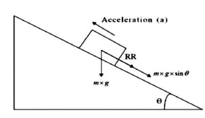
Figure 7. Illustration of a Vehicle's Free Body Travelling Up an Incline.
In this case, the gradient is moved up by the (+) symbol and down by the (-) sign.

= 72.7440 N

where,
C = Drag Coefficient = 0.5
ρ = Air pressure in kg/m3 = 1.1644
V = the speed in m/s = 9.7222
A = Area in Front = 0.7

= 19.2606 N

Therefore, the power required to drive a vehicle is
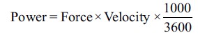

= 959.34 watt
5.2.4 Breaking Force
Time require to stop the object = 5 sec
M = 170 kg
V = 35 kmph
V = 9.73 m/s
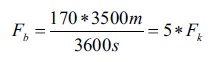
=1652.7=5*Fk
where F = Frictional force
Fk = k*Fb
Iron friction coefficient k = 0.4
= 0.4*Fb
Fb = 826.35 kg m/s2
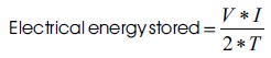
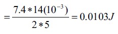
5.2.5 Electrical Energy
O/P voltage = 7.4 v
Speed = 731 rpm
O/P current range = 14 mA
Time required to stop Δt = 5s
5.2.6 Rotational Kinetic Energy
N=731 rpm
Tire weight = 10 kg
Radius of wheel = 0.254 m
Moment of inertia of two wheel (I) =2*MR2
=2*10*(0.254)2
=1.2903 kgm2
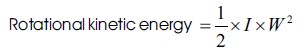
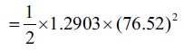
= 3776.6 J
5.2.7 Breaking Energy
M = 170 kg
Vf = 0
Vi = 35 kmph = 9.73 m/s
= 1/2 (M) (Vi2 - Vf2)
= 1/2 (170) ((170)2 - (0)2)
= 8047.19 J
However, power regeneration of each brake is 12 V × 1.75
A = 21 Watt
So, for each brake 21 watt is saved.
Let's say for ten brakes,
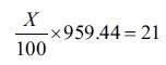
Thus X=2.2 %
Hence 2.2 % braking results in power savings. Thus Added travel mileage is 2.2 % of 35 km.
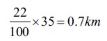
Thus,
Total distance covered = 35 Km + 0.77 Km = 35.770 Km
5.2.8 Comparison of Lithium-Ion and Lead-Acid Batteries
The comparison between lithium-ion and lead-acid batteries is tabulated in Table 1. Lead acid batteries offer better quality, efficiency, and lifetime than lithium-ion batteries. However, lithium-ion batteries are more expensive, but their higher performance and longer lifespan can make them a more cost-effective choice in the long run. The choice between the two types of batteries will depend on the specific requirements of the electric vehicle and the available budget.
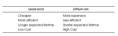
Table 1. Comparison of Lithium-Ion Battery and Lead-Acid Battery.
5.2.9 Comparison of Mid-Drive and Hub-Motors
Table 2 compares mid-drive motors and hub motors. Both types of motors can be equipped with regenerative braking systems, which convert the kinetic energy of the vehicle into electrical energy to recharge the battery. However, mid-drive motors are generally more efficient at regenerative braking because they can use the drivetrain to help slow down the vehicle, while hub motors rely solely on the braking force of the wheel. Choosing between a mid-drive and hub motor depends on several factors, including the type of EV being designed, the intended use, and the budget. Mid-drive motors offer better torque control and are more efficient at regenerative braking, but they require more maintenance and are generally more expensive. Hub motors, on the other hand, are simpler and require less maintenance, but may not provide the same level of control and efficiency as middrive motors.
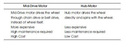
Table 2. Comparison of Mid-Drive and Hub-Motor are Contrasted
6. Results and Analysis
The results and analysis of designing an electric vehicle with a regenerative braking system includes an analysis of the vehicle's performance, such as speed, acceleration, and range. The section on energy consumption and efficiency would analyze the vehicle's energy usage and efficiency with and without regenerative braking. Also, it would provide a detailed and comprehensive evaluation of the electric vehicle's performance, energy consumption, efficiency, and cost, as well as a comparison with conventional vehicles. Figure 8(a) shows the engineers who designed the scooters, while Figure 8(b) shows the designed scooter.
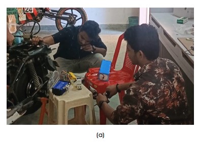
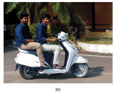
Figure 8. (a) Scooter Designing By Designers (b) Designed Electrical Scooter
This results in a reduction of our fuel usage by 10% to 25%. Regenerative brakes utilize the energy collected to recharge the car's batteries, providing each car with an extended charge while traveling that would otherwise be lost. When a halting order is issued to the BLDC motor after it has been driven, the motor will stop after a certain amount of time due to its inherent inertia (Lee & Nelson, 2005), resulting in the production of Electro Motive Force (EMF). During this time, regenerative braking will also be activated, producing back up EMF in the braking system (Bobba & Rajagopal, 2010). Once the voltage reaches the battery level, the back up EMF will begin charging the battery. In some cases, regenerative braking can even extend the range of your electric vehicle up to 50% when driving downhill. The output results of the experiment are shown in Table 3.
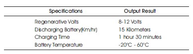
Table 3. Output Results
Conclusion
The regenerative braking system in electric vehicles has been discussed as one of the key components that can reduce energy waste by 8 to 25%. This system enables the expansion of the vehicle's range by using the saved energy to power accessories on an e-scooter, or lengthening the daily commute. Research has shown that regenerative braking is already in use in many electric vehicles, and the rising fuel prices have led to further research and improvements in energy conservation. It is important for electric cars to utilize the electric power produced by the motor, generator, and battery. The completed project has found that the RBS is a fantastic idea that has motivated both automotive and electrical engineers and deserves further research.