Figure 1. SRM Section
Switched Reluctance Motor (SRM) suffers from current ripples and speed oscillations due to variations in loading conditions. Most of researches focus on enhancing the performance of SRM through speed and current controllers. This paper proposes two relatively new strategies to enhance the performance of the SRM. First one is optimizing the gain of classical proportional integral (PI) controller using sine-cosine optimization (SCO). The other strategy is to use adaptive PI controller. The proposed techniques are evaluated under several loading conditions with the proposed strategies applied in the current control system. The results deduced the superiority of adaptive controller under all loading conditions presented.
Machines can be categorized regarding to the way of torque production into two categories which are the variable reluctance category and the classical electromechanical one (Hamouda & Számel, 2020; Wang et al., 2020). In the electro-mechanical category, the motion is produced through interaction between the fields generated from the stator and rotor. While in the second category the reluctance between the stator and rotor is variable and this variable reluctance is responsible for the motion. Switched reluctance motor (SRM) is one of the second category machines. SRM performance is enhanced through the improvement in power electronics tools (Bian et al., 2020). Also, the construction of this type is very simple which helps in the growth of the SRM in applications (Kondelaji et al., 2020).
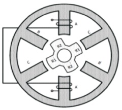
The SRM produces torque when the excitation winding at the position of maximum inductance is tangent to the moving of the movable parts (Miller, 2001). SRM section is shown in Figure 1.
Figure 1. SRM Section
Figure 2 illustrates the drive components of the SRM which are the converter for each phase, controller and the motor. The torque production is through controllers which try to adjust the rotor poles motion to get maximum inductance so the current direction doesn't affect the torque production (Wang, 2014).
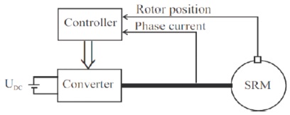
Figure 2. SRM Drive
Regarding to Wang (2014), the SRM condition to start is the number of stator poles not equal to the number of rotor poles. The speed torque characteristics of SRM is shown in Figure 3 (Wang et al., 2020).
Regarding to Figure 3, the operating point of SRM is at maximum power which is constant. This operating point happened when the emf of motor and the DC source is equal. If the speed is increased this led to reduction in power due to increase of emf (Wang et al., 2020). Equations (1) to (4) presented the nonlinear equations of SRM (Kondelaji et al., 2020; Miller, 2001; Wang, 2014).
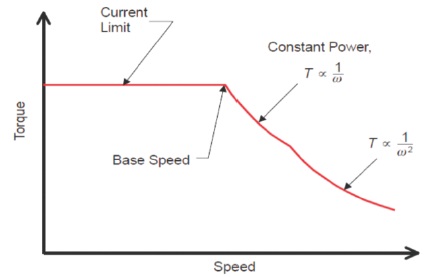
Figure 3. Speed Torque Characteristics of SRM
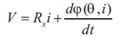
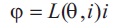
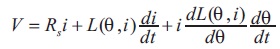
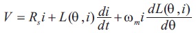
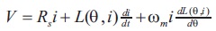
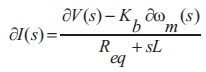
Where V is the machine terminal voltage, I is the current, L is the variable inductance, θ is the position, Rs is resistance/phase, Φ is flux linkage/phase, the angular speed  . From Equations (1) to (4) equivalent circuit can be deduced as shown in Figure 4.
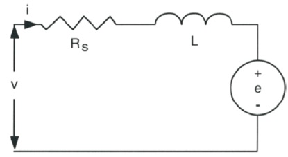
Figure 4. SRM Equivalent Circuit
Kondelaji et al., (2020) presented the emf of the SRM as shown in Equation (5).
As most of artificial intelligent methods, the SCO starts with random population then this population is updated through updating of solution position as shown in Equations (6) and (7).
where Xit+1new solution position, X it t-iteration solution position and r1, r2, r3 are random adjusting variables (Mostafa Elsaied et al., 2018). Another variable r4 is used to transfer between Equations (6) and (7). Flow chart of SCO is shown in Figure 5.
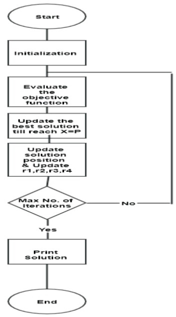
Figure 5. SCO Flow Chart
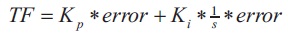
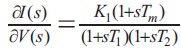
The Proportional-Integral (PI) controller is considered as one of the most common used controllers in industrial applications. It consists of two parts. The first one is proportional which is a gain (Kp) multiplied by error. The second part is integral which is a gain (Ki) multiplied by the integration of error. The transfer function (TF) of PI is shown in Equation (8) (Johan, 2002).
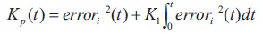
To enhance the performance of classical PI which has fixed gains, adaptive PI controller is presented which changes the gains continuously regarding to any disturbances. The adaptive PI proposed in Mokhtar et al. (2017) is used here. Equation (9) describes the operation of this controller.

where K is constant while Kp and Ki are updated as shown in Equations (10) and (11).
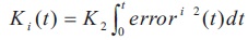
where K1 and K2 are the adjusting constants.
Model of SRM is built from two categories of equations. These equations are the torque equations and the general equations as presented in the next sections.
The torque production of SRM is based on conventional energy conversion as presented in Equations (12) to (17) (Miller, 2001).
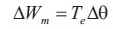

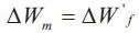
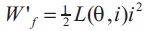
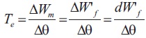
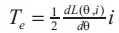
where L(θ,i) is stator inductance, I is Current/phase, Te is torque produced, Δθ is Change in angle of rotor, W't is unsaturated magnetic co-energy
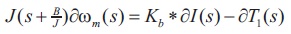
From these equations the total torque can be deduced as presented in Equation (18) (Sasmal & Mula, 2015).
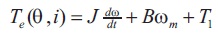
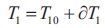
Where J is Moment of inertia, B is friction coefficient, and T1 is torque of load.
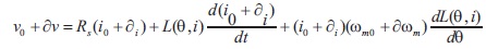
The voltage of SRM can be presented as in Equation (19).
The inductance is assumed to be constant, then the SRM voltage, current, angular speed and torque can be presented as shown in Equations (20) to (23).

Then using Equations (20) to (23) in Equation (19),
Then,
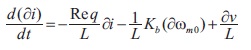
Where, 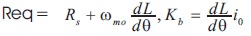
Then,
Equations (25) and (26) will be presented as in Equations (27) and (28) at frictional load.
Thus,
Where,
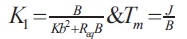
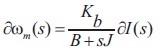
Figure 6 presents the block diagram of the system neglecting the torque of the load.
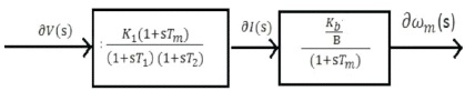
Figure 6. The SRM Block Diagram Neglecting the Torque of Load
The SRM with the controller is shown in Figure 7.
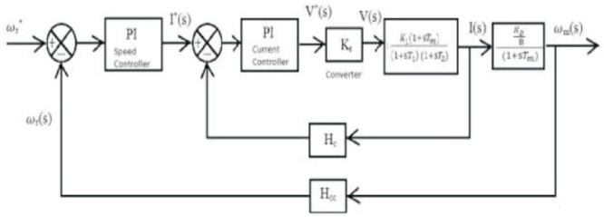
Figure 7. SRM with Controllers
Parameters of the SRM are shown in Table 1.
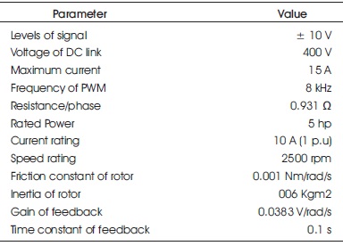
Table 1. Parameters of SRM
The load is assumed to be 25.4 Nm, and also the reference speed is selected to be 157 rad/s (Hussien & Attia, 2017). The speed profile is assumed as shown in Figure 8.
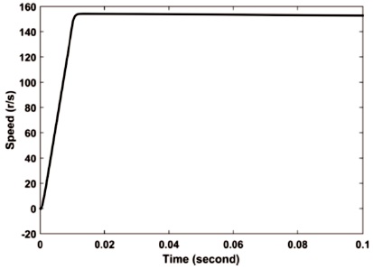
Figure 8. Speed Profile under Loading 25.4 Nm
Two control strategies will be applied, the first one is classical PI controller which will be used in speed and current controllers. These controllers will be optimized using SCO technique. The second strategy is using optimized classical PI controller in the speed controller and adaptive PI controller in the current controller. The Simulink model is shown in Figure 9.
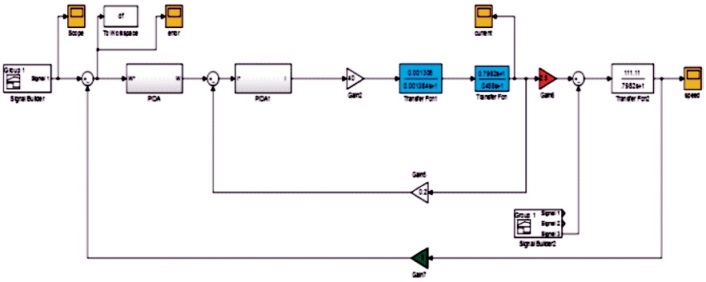
Figure 9. SRM Simulink Model
First, The SCO technique is used to tune the parameters of the classical PI controllers in the speed and current controller. The gains were adjusted to be 1 (i.e., Kp1 = Kp2 =Ki1 =Ki2 =1). Then, the classical PI in the current controller is replaced by the adaptive PI to compare the results obtained from the two techniques. The Figures 10, 11, 12 and 13 illustrates the speed and current under load applied in the starting in case of classical and adaptive controller respectively.While in Figures 14, 15, 16 and 17 illustrates the speed and current under load is applied at time t= 0.005 s. Finally, Figures 18, 19, 20 and 21 illustrates the speed and current under loading at t=0.04 s.
It is clear that, the recovery of the system is smoother in case of adaptive controller and the steady state error in speed is improved than the classical controller results as shown in Figures 10, 11, 12 and 13.
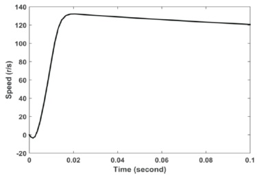
Figure 10. Speed Profile using Classical Controller–load Applied at Starting
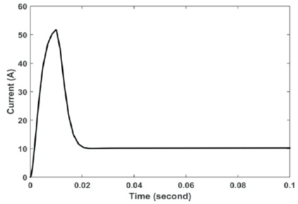
Figure 11. Current using Classical Controller–load Applied at Starting
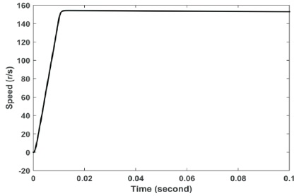
Figure 12. Speed Profile using Adaptive PI at Current Controller–load Applied at Starting
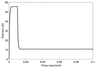
Figure 13. Current after using Adaptive PI at Current Controller–load Applied at Starting
From Figures 14, 15, 16 and 17, the adaptive controller proved its superiority through fast recovery and lower steady state error in speed profile than the classical controller.
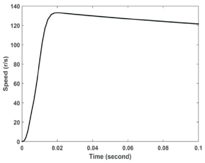
Figure 14. Speed Profile using Classical Controller–Load Applied at t=0.005 s
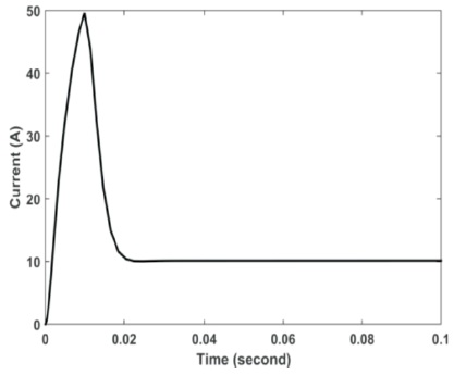
Figure 15. Current using Classical Controller–Load Applied at 0.005 s
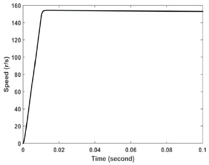
Figure 16. Speed Profile using Adaptive PI at Current Controller–Load Applied at 0.005 s
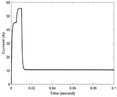
Figure 17. Current after using Adaptive PI at Current Controller–Load Applied at 0.005 s
Finally, the adaptive controller still proved its superiority where it succeeded again to recover the current faster than the classical PI as shown in Figures 19 and 21.
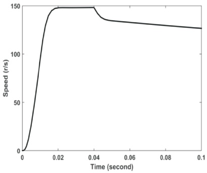
Figure 18. Speed Profile using Classical Controller–Load Applied at t=0.04 s
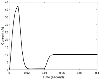
Figure 19. Current using Classical Controller–Load Applied at 0.04 s
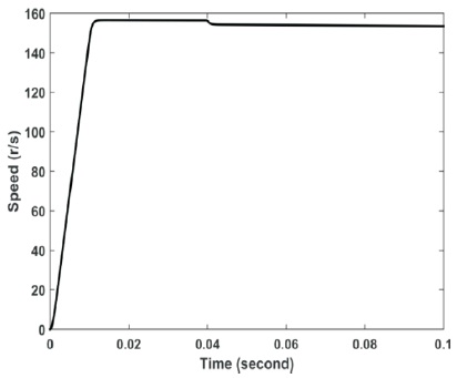
Figure 20. Speed Profile using Adaptive PI at Current Controller–Load Applied at 0.04 s
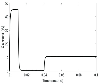
Figure 21. Current after using Adaptive PI at Current Controller–Load Applied at 0.04 s
In this work, two control strategies are used to enhance the performance of SRM. First one depended on the classical PI controller. The other strategy depended on the adaptive PI controller. Several cases are studied under sudden loading conditions applied at different time instants. The adaptive controller proved its superiority than the classical PI through smoothing of speed and current profiles of SRM. Also, the adaptive controller had fast recovery and lower steady state error after the loading disturbances.