
Figure 1. Block Diagram of Transmitter and Receiver End
This paper presents a technique by which we will get realtime data of an induction motor and controlling its speed using PLCC (Power Line Carrier Communication). The main aim of using power line carrier communication is to utilize the already existing power cable for data transferring and communication. We can apply this system usually in small areas such as house, offices, etc., by which we can control various kinds of system remotely and this will help to make work efficiently through automation. In this project we are controlling the speed of single phase induction motor and collecting its realtime data through PLCC system. In order to control speed of induction motor, TRIAC circuitry is used.
There are different methods available for transmitting data and information signal such as Ethernet cable, fiber optics cable, telephone lines wireless transmission, satellite transmission, etc. (Patil et al., 2016). For each and every type of communication methods we require a whole new set up which increases the cost of data transmission. Hence, we need reliable and cost effective system for data transmission and therefore PLCC system is one which perfectly fits into this criteria (Serrao et al., 2012).
PLCC (Power line carrier communication) is the technology that uses the existing power line or power cable in our surrounding for data transmission and controlling the system. PLCC is also known as Power Line Networking (PLN), Band Over Power Line (BPL) and Power Digital Subscriber Line (PDSL) (Akarte et al., 2014; Jangir, 2012). In today's world everyone has AC power lines installed in our house, offices, etc. Therefore, in present scenario this system can be used in homes and offices automations (Palpankar et al., 2015) as this system reduces the cost of separate wiring for data transmission (Serrao et al., 2012).
The power line carrier communication is used for data transmission based on remote control with status feedback in alternative technology to the GSM and radio frequency technology (Basha et al., 2016). This system has also been used for electrical meter reading of consumer by electricity department (Sathishbaboo et al., 2017). Speed control of an single phase induction motor is utilized in various place such as fan load blower centrifugal pump (Sharma et al., 2016).
Our project is focused on the application of power line carrier communication as well as utilization of speed control of single phase induction motor. Our model operate at range of 150 KHz carrier frequency and extracted in 230 V, 50 Hz. For this we are using PLCC or KQ330 module. This project is controlled by microcontroller ATmega328 in which internal coding is done by embedded C. And the speed of single phase induction motor will be controlled by a TRIAC circuit. We will also be using LabVIEW software for giving command for switching of loads, speed variation also to view realtime current variation. We have also placed LCD screen to display the frequency and speed variation.
This project can be utilized for home automation purpose as well as industrial motor controlling purpose.
The transmitter part will be used to send the data signal along with carrier signal to its destination without interruptions with the help of already existing power cable as shown in Figure 1. At receiver part the data signal is demodulated which is supplied to micro-controller in order to run our project. The realtime data signal will be send to PC's for display of current and voltages.
Figure 1. Block Diagram of Transmitter and Receiver End
Our project has three parts, i.e., first part is the transmitter, second part is receiver and third is its control circuit. Transmitting and receiving ends are connected through power cable. Both sides contain PLCC Module KQ330 which is used for modulation and demodulation of the signal transferred. Figure 2 is our project image and Figure 3 is circuit diagram of our model. LABVIEW software has been used to control our model and also used to view the output of appliance (Palpankar et al., 2015).
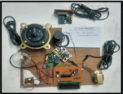
Figure 2. Hardware Model of our PLCC Project
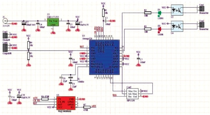
Figure 3. Circuit Diagram of our PLCC Project
The transmitter circuit consist of PC or laptop which contain LabVIEW software, a serial port communicator and PLCC module. This end is used to control loads and give final outputs.
At receiver side PLCC module connected to power line is further connected to micro-controller ATmega328 and TRIAC circuit. For testing purpose, we have used two load, a single phase induction motor and a bulb; both are connected with ACS712 current sensor. This current sensor is further connected to the microcontroller ATmega328 in order to provide the realtime current value of load. This end consist of control circuit for our loads, i.e., speed control of an Induction motor and switching of bulb. However, while connecting the receiver module we should connect it on the same phase.
This control circuit consist of direct power supply, triggering circuit and TRIAC circuit.
The power supply circuit provides AC 230 V, 50 Hz though step down transformer which is used to step down voltage to 12 V and further this voltage is converted into DC voltage. This DC supply has been used to run the electronic component such as TRIAC, optocoupler and microcontroller in our project .
Secondly, it has triggering circuit which consist of zero cross detector circuit along with optocoupler. Here, zero cross detector circuit detects zero point of input signal and provide delay for desired firing angle. Usually this delay is controlled by microcontroller ATmega328. However, optocoupler is an electronic component used to connect two separate electrical circuit using light signal and in our project it is used to trigger TRIAC. In this circuit is that we can control the RMS voltage in both the direction.
In TRIAC circuit, TRIAC is main electronic component which is used to conduct in both direction when it is triggered through gate. This is used for switching high voltage or high value current in both positive and negative half cycle of AC wave form. This is operated by microcontroller Atmega 328. This is connected in series with load and used to increase and decrease the speed of induction motor. We have used BT139 TRIAC. Micro-controller ATmega328 is used to control whole operation. This microcontroller provides signals from transmitter end with the help of LabVIEW interface. Microcontroller has been used to operate TRIAC circuit and display feedback of current on LabVIEW interface. This provide triggering pulse or firing pulse to TRIAC circuit which is connected in series with load. When there is change in speed there is also change in the current. This current is detected by current sensor ACS712 which is connected to microcontroller. Through microcontroller this signal is send to LabVIEW software in order to display in interface, and speed and frequency will be displayed on LCD screen.
LabView (Laboratory Virtual Instrument Engineering Workbench) is a system engineering software which is used for application that requires test, measurement and rapid control access of hardware model. For controlling of our hardware project we have designed a LabVIEW model. Figure 4 is operational model or operation ladder of our project.
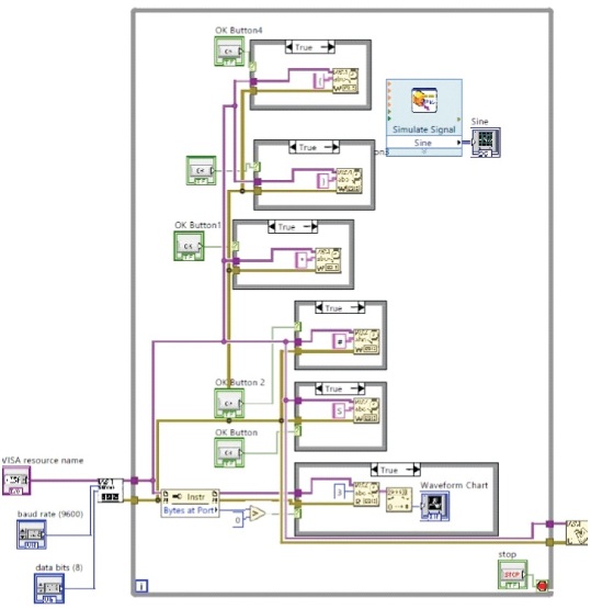
Figure 4. LabVIEW Operational Model
This LabVIEW ladder diagram is designed to control the speed of single phase induction motor as well as monitoring its realtime data such as current and voltage. In LabVIEW interface we have created different button such as START, STOP, OK BUTTON AND OK BUTTON2 for increasing and decreasing the speed of motor. Similarly OK BUTTON4 and OK BUTTON5 is used for switching (ON/OFF) of bulb. It has 8 bit data, and the baud rate is 9600.
Our project uses power line for data and controls signal transmission. Therefore, while connecting transmitter ends and receiver end to the main supply line, it should be connected on same phase as shown in Figure 5.
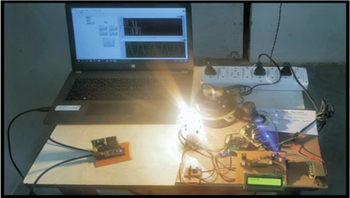
Figure 5. PLCC Running Model
After connecting to main supply we will connect the transmitter end to our PC, from where we will operate our hardware using LabVIEW interface. We will first give start command using Start button and select COMP on the screen. Then we will increase the speed of motor using OK BUTTON and then we will press OK BUTTON 3. Pressing OK BUTTON 3 we will get the realtime current of the single phase induction motor. The speed and frequency will be displayed on the LCD screen. Similarly we can switch on bulb by pressing OK BUTTON 5, after pressing OK BUTTON 3 we will get the realtime current of motor and bulb together. And by pressing OK BUTTON 4 we can switch off the bulb. In LabVIEW interface we will get the input voltage graph and current graph will be plotted as speed of motor when we press OK BUTTON3. This variation of current can be plotted in the table form as shown in Figure 6 and the final output is displayed in the LabVIEW interface in graph form. At the same time frequency and speed change will be displayed on LCD screen. The observed value are shown in Table 1 and Table 2.
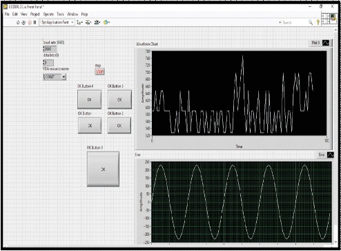
Figure 6. LabVIEW Interface with Real Time Current and Voltage Graph
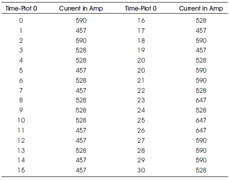
Table 1. Table for Time-Current
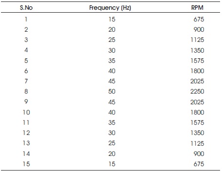
Table 2. Variation of Frequency and Speed
In this paper, control signal which we have sent from transmitter end in power line using PLCC module is controlling the speed of motor and switching of bulb. Similarly, when we press OK BUTTON 3, the microcontroller receives the signal and provides the real time current of single phase Induction motor or load which is plotted on the LabVIEW screen. This change of current with respect to time plotted in table form is shown in Table 1. At the same time we also get frequency and speed on the LCD screen which has been plotted on Table 2. When we press increase button, frequency and speed will increase and when we press decrease button speed and frequency will decrease.
Therefore, by using this method we are able to utilize the existing power line to control and collect realtime data for monitoring the single phase induction motor. It is a reliable and cost effective system for data transmission and control.
This work has been supported and guided by faculties of Department of Electrical Engineering, Shri Shankaracharya Group of Institutions, Bhilai, Chhattisgarh, India.