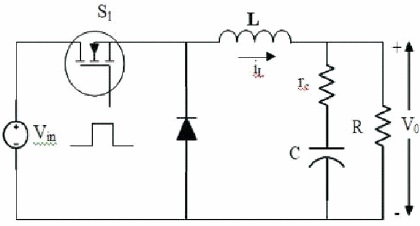
Figure 1. Buck Converter Design
A DC-DC converter is a electronic circuit that synthesis different DC voltage levels from DC source. DC-DC converters has wide range of applications in Industries, automotive and transportation, electrical appliances and so on. Objective of this paper is to model a DC-DC converter which controls the converters output and keeps it constant irrespective of change in the input parameters. The Pulse Width Modulation, Proportional Integral Controller, Proportional Derivative Controller (PID) and Proportional Integral Derivative Controller are the well known methods known to control DC-DC converter. But the performance shows deviations when there is large parameter in load. This is why adaptive non-linear controllers such as Fuzzy Logic Controller (FLC) is used. The non-linear controllers provides a much faster response compared to linear controllers. Thus in this paper we have simulated and compared PID controller with FLC controller for DC-DC converter using MATLAB / SIMULINK. Further a new scheme of cascading FLCs is implemented to improve the performance.
The DC voltage from controlled/uncontrolled rectifiers, renewable energy sources is unregulated in nature. DC/DC converters supply a fine and adjustable DC voltage to a variable load from such unregulated DC sources. These converters are utilized in applications such as battery chargers, renewable sources integration, maximum power tracking in solar PV, DC motor drives etc. Conventionally, analog controllers have been used for obtaining controlled output from DC/DC converters. Digital control of DC/DC power converters is more finer than analog control as the advanced control algorithms like adaptive control and non-linear control can be simply executed by utilizing digital control. DC-DC converters are extensively used today in power processing for regulated power supplies, electrical drives, renewable energy conversion system, electric traction etc. The dynamic performance of DC-DC converters can be enhanced by application of robust control schemes such as fuzzy logic controller. DC-DC converters shows non-linear peculiarity due to fluctuating operating points, which affects performance of converter.
To achieve better performance, there are two solutions. One is to develop more exact model of converter and second is to use a non-linear controller. The exact model of system is extremely complex to use for controller design. A FLC is capable of adapting fluctuating operating points, so it is utilized as non-linear controller for DC-DC converters. To obtain stable operation of buck and boost converter, classical PI and FLC based control strategy is presented. To rectify the problem of nonlinear nature of DC-DC converter, a FLC is used as it does not require precise mathematical model of plant. A general FLC design that can be used for wide variety of DC-DC converters is inspected in reference. Robustness of FLC is demonstrated in presented work by obtaining results for practical operating conditions of DCDC converter such as, varying input voltage. The proposed FLC can be used for other configurations of DC-DC converters without or small modifications in rule base. The two controllers designed in this paper are, PID controller and a FLC. Since they have a reprogramming ability by changing the rule base, a new cascading scheme for FLC is also designed and implemented using MATLAB / SIMULINK.
In their paper, Raviraj and Sen (1997) have used automatic mode-shifting control strategy with input voltage feedforward for full bridge-boost DC–DC converter. But due to the existence of many nonlinear devices in the system, it is difficult to accurately calculate the transfer function of the system and the compensator.
Baasandorj et al. (2014) studied on load current feedforward control strategy for PWM rectifier. They introduced a load current feed-forward control method for PWM rectifier. It achieves good effect on PWM rectifier. The calculation is improper and the dynamic performance will be degraded. At the same time, function calculation will take up a lot of processor resources, resulting in the decrease of control frequency.
A comprehensive analysis and hardware implementation of control strategies for high output voltage DC-DC boost power converter is made by Gupta et al. (1997). Design of a digital controller for buck converter by using state-space average (SSA) technique is presented in Figure 1. To obtain stable operation of buck and boost converter, classical PI and FLC based control strategy is presented. But it has less efficiency compared to other techniques.
Figure 1. Buck Converter Design
In their paper, Caldo et al. (2013) made a fuzzy logic controlled parallel connected synchronous buck DC-DC converter for water electrolysis. A FLC for full-bridge soft switching converter is designed and verified. A DC-DC converter is proposed for solar energy-hydrogen conversion system and as the electrolysis load is nonlinear, FLC is a choice in place of other linear controllers. In digital design and hardware implementation of FLC using DSP is demonstrated.
A buck converter is designed for some parameters which we will be used as a reference circuit of buck converter for further processes. Buck converter design parameters and values of components are displayed in Table 1. Control-tooutput transfer function as shown in Figure 2 is used for development of controller for converter ( Rashid, 2016). There are small signal perturbations of output voltage and switching duty cycle.

Table 1. Buck Converter Design Parameters

Figure 2. Structure of FLC Controlled Converter
Fuzzification: Each input data is mapped to the degree of membership function. This matching is done as per the conditions given by the rule base. For each linguistic term which applies to the input variable a degree of membership exists.
Rule base: Rule base is nothing but a set of rules. The rules used in fuzzy logic are generally “if and then” statements where the if stands for condition and then stands for conclusions. For the designed system depending on the measured inputs i.e., error (e) and change in error (ee) computer executes these rules and give a control signal. Even for an inexpert user it is easy to understand the implementation of rule base.
Inference Mechanism: This mechanism decides the control rule that is suitable for the particular situation and respectively gives the input to the plant.
Defuzzification: The combination of all the decisions (that are been taken) into a single non fuzzy output signal is called defuzzification process. Various defuzzification methods are used for this purpose.
Using fuzzy toolbox in SIMULINK, two inputs and one output to and from fuzzy controller tool box are mapped in universe (-1 to 1) and .fis file in MATLAB/SIMULINK is obtained.
The basic fuzzy algorithm is represented for buck converter. Fuzzy logic control configuration for buck converter is shown in Figure 2 and same method is used in implementation. Figure 3 shows three sections of fuzzy control algorithm.

Figure 3. Fuzzy Logic Tool
The logical operator used for rule base is AND operator. Following are the six linguistic variables used for error and change in error.
A single level is given to each input and output. That is each input and output is given a membership grade to every fuzzy set. To reduce the complexity in calculations, triangular and trapezoidal type of membership functions are used. Table 2 shows normalized values of error and change in error. Figure 4, 5 and 6 shows the membership functions of input error, input change in error and output change in duty cycle respectively.
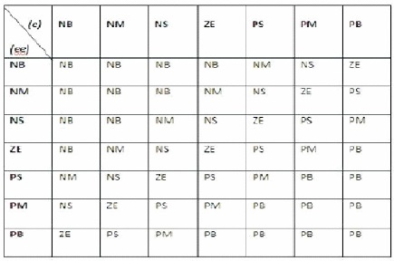
Table 2. Rule Base for Buck Converter Using Fuzzy
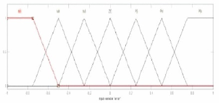
Figure 4. Membership Function for Input Error
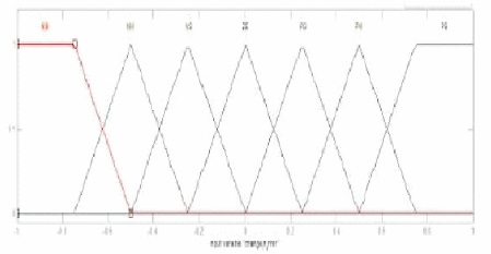
Figure 5. Membership Function for Input Change in Error
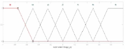
Figure 6. Membership Function for Output Change in Duty Cycle
Here we simulated the buck converter with PID converter as well as buck converter with fuzzy logic controller with varying input voltage. The output is tabled and compared.
Here the reference buck converter is designed with feedback loop control of PID controller. The PID controller is designed using auto tuning mechanism in SIMULINK as shown in Figure 7. The Table 3 shows the output response of the design for varying input voltage. Figure 8 provides the output waveform of buck with PID.

Table 3. Output Voltage of PID with Varying Reference Voltage
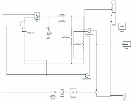
Figure 7. Buck Converter with PID Control
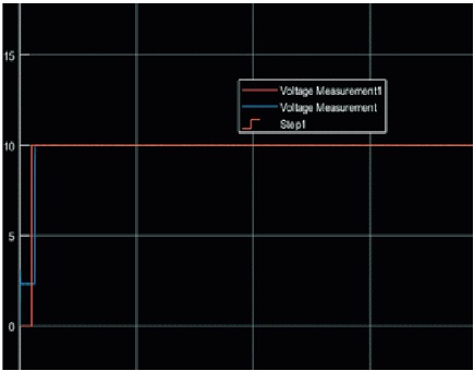
Figure 8. Output Waveform of PID with Varying Input Voltage
The fuzzy logic which has been built before is used as a feedback loop with the reference buck converter designed. Figure 9 shows the design of the buck converter with the fuzzy logic controller.
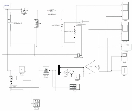
Figure 9. Buck with FLC Design Scheme
The fuzzy logic output is compared with the varying output as we did for PID controller as shown in Table 4. The output waveform is shown in the Figure 10.

Table 4. Output Voltage of FLC with Varying Input Voltage

Figure 10. Output Waveform of FLC with Varying Input Voltage
Here we have designed a new scheme of FLC for the same buck converter with cascading scheme. From this cascading we can see that the output efficiency of the normal FLC scheme is increased. Figure 11 shows the cascading scheme of FLC with the buck converter. Table 5 shows the output voltage of the new scheme with the varying input voltage. Figure 12 shows the cascaded FLC output waveform. As we can observe the efficiency of the controller is increased compared to the normal FLC scheme. Even the output waveform provides a greater response compared to the normal response of the FLC. This comparison is shown in Figure 13.
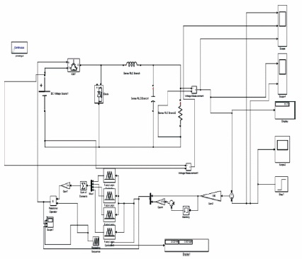
Figure 11. Cascaded FLC Design Approach
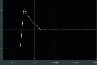
Figure 12. Cascaded FLC Output Waveform
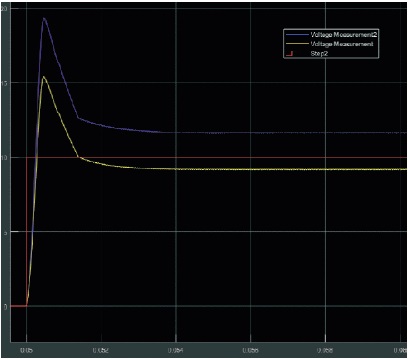
Figure 13. Comparison of Fuzzy with Cascaded Fuzzy
In this paper, design of robust FLC and PID controller for DCDC buck converter is presented and simulated. Simulation results are obtained for practical operating conditions such as: varying input voltage, varying load resistance and reference voltage tracking. Simulation results shows that, as compared to other standard controllers FLC yielded better performance in terms of low overshoot and settling time. The FLC is able to adapt itself to other configuration of DCDC converters. So, the design of FLC presented in this paper can be used as a general controller for DC-DC converters. The PID controller demonstrated in this paper for DC/DC converter is designed using digital re-design approach. To obtain desired characteristics form, the controller takes less memory size and less time to execute due to reduced complexity of architecture. MATLAB/ SIMULINK based simulation results are obtained for practical operating conditions, which show that the digital control effectively improves the performance of DC/DC converters under disturbances. The two controllers presented in this paper have their own advantages. FLC is a robust controller that can deal with the non-linearity of the converters and PID based controller have simple architecture suitable for their fixed point implementation.