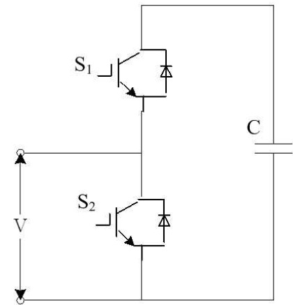
Figure 1. Half Bridge Sub-Module
An appreciable and significant measure of interest is currently growing up for power DC-DC converters, modernly in the industries and the civilized society and associations. In present days, the DC-DC converters are one of the most preferred and recommended choices for the use of medium and high power utilization functions in order to achieve the objective of electronic power conversion. High voltage AC-DC, DC-AC, and DC-DC converters being the essential fundamental unit of the HVDC transmission system in order to coordinate and fulfill the requirements of the power generating stations, AC grid and loading stations. Modular Multilevel Converter (MMC) holds some remarkable features, such as modular design, scalability, reliability, tolerance of failures and larger step up and step down ratio, that make it an essential and meaningful topology for HVDC system. This paper gives an evaluation and assessment over various configurations of higher voltage DCDC MMCs; its working along with characteristic attributes. Furthermore, it explains the modulation and control technique considered for DC-DC MMCs.
Recently in present days, the implementation and investigation over Modular Multilevel Converters (MMCs) have full-fledged rapidly over the preceding couple of years (Akbar & Hasan, 2018). Modular multilevel converters were first developed by Dr. Lesnicar to be used for high voltage applications The Modular Multilevel Converter (MMC) is among the one of the most part of outstanding converter topologies that is being utilized for the use of both high as well as medium power conversion, particularly for high voltage direct current (HVDC) transmission systems (Debnath, Qin, Bahrani, Saeedifard, & Barbosa, 2014). Recently the industries and the educated community have MMC as one of the preferred choices in medium and high power applications for the purpose of electronic power conversion (Perez, Bernet, Rodriguez, Kouro, & Lizana, 2014). The MMC based DC-AC-DC converter is also applicable for extensive large voltage stepping ratio application (Purkait & Pandey, 2018a).
Modular multilevel Dual-active-bridge (DAB) with Input Series Output Series (ISOS) configuration can be featured for high voltage DC-DC power conversion, although the foremost drawback of this converter is the necessity of greater number of isolation transformers with elevated potential winding variations, it also requires large number of semiconductor devices and DC capacitors (Solas et al., 2013b). Controlling and auditing the various capacitor voltages and arms currents is very important to establish and safeguard the operation of equalized capacitors voltages (Peng et al., 2016). As a result of which the complications of the control system increases, and also affects its reliability (Peng et al., 2016).
The label of MMC have been extended to represent a huge family of power electronics converters depending on the series connection of the N number of sub-modules (SMs) with single inductor (L), constructing the two arms of the converter and utilizing a one individual dc source for the converter (Konstantinou, Zhang, Ceballos, Pou, & Agelidis, 2015). The number of sub-modules chosen depends on the power capacity and applications, which will be employed. Multiple connections of capacitors are done with each of the sub modules, which results in form of minute current flow from the capacitor and reduced losses (Purkait & Pandey, 2018b). Each of the sub-modules can be placed in the converter circuit in order to modify or tune the output generated by the converter in form of voltage, current, and frequency (Bahrani, Debnath, & Saeedifard, 2015). The high step-up and step-down voltage ratios that are assembled by modifying the number sub-modules, which are linked and allied in series of MMCs along with the use of bulky transformer can be escaped off (Darus, Konstantinou, Pou, Ceballos, & Agelidis, 2014). While exploring and comparing with different multilevel converter circuits, the important and significant attribute of the MMC include:
The most often and frequently used realization or configuration of the sub-module is half bridge structure (Kenzelmann, Rufer, Dujic, Canales, & De Novaes, 2015). Figure 1 represents the half bridge structure of the converter sub-module consisting of two switches, working in a complementary behavior along with a capacitor generating different voltage levels (You & Cai, 2018). HB-SM is the most commonly used circuit structure because of small losses and its clear, easy and understandable structure and control operation.
Figure 1. Half Bridge Sub-Module
The full bridge configuration is the simplest fully controllable structure. As shown in Figure 2, the full bridge configurations of the converter sub-module consist of four switches and a capacitor. It can produce both positive and negative voltage at its output terminals. This type of sub-modules produce higher losses than the HB-SM, but can also produce high step-up voltage in DC to AC power conversion.
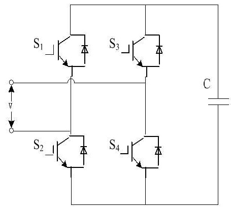
Figure 2. Full Bridge Sub-Module
The clamped double sub-module structure is substitute to two series-connected half bridge sub-module as represented in Figure 3 and is efficient enough to produce negative voltages at its output terminals; this type of submodule can reduce the number of semi-conductors connected in series in the conduction path in comparision with the full bridge sub-module. The configuration of the SM also be operated at lower frequencies and thus it can also minimize the capacitor voltage ripples.
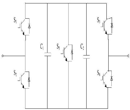
Figure 3. Clamped Double Sub-Module
The extension of the HB-SM is based on the flying capacitor converter is shown in Figure 4. Every single sub-module comprises of capacitors at distinct level of voltage and thus it needs supplementary balancing of voltages of the capacitors along with the control over the phase leg and arm energy and voltages. Apparently in theories numerous multiple levels can be obtained, but due to the appearance of the voltage balancing problem of the flying capacitor converter, the practical implementation is accomplished up to three levels FC-SM.
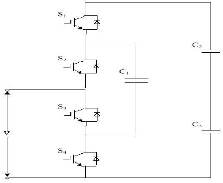
Figure 4. Flying Capacitor Sub-Module
1.4.1 Principle Operation of Sub-Module
The modular multilevel converter's operating principle using the half bridge sub-module most frequently used has been described here. During the converter operation when the gate pulse is provided to the switches of the converter the output voltage produced at the sub-module terminal is moreover equivalent to the capacitor voltage Vc otherwise zero. Ideally, the value of Vc is equal to Vdc/n. The switches of the sub-module are complementary in its behavior, i.e. when one of the switches is ON, the other switch is automatically switched OFF. When first switch is ON and another is OFF, the voltage induced at the terminal of the sub-module is same as that of the voltage of capacitor. Depending on the direction of current flowing through the sub-module, the capacitor starts charging or discharging. In the opposite case, when the first switch is switched OFF and the second switch is switched ON, the capacitor gets bypassed and the voltage induced at the terminal of the sub-module is zero. The voltage of the capacitor cell remains same as long as it is bypassed. Both the switches of the sub-module can be switched OFF during the time of start up so that the capacitor can get charged to its initial value. Both the switches cannot be switched ON at the same instant of time, as it may lead to short circuit of the system. To achieve appropriate operation of MMC each capacitor, cell voltage should maintain an ideal value near to Vdc/n.
The MMC based DC-DC converter is recommended with elasticity and adjustable expansion of reduced harmonics followed by fault isolation (Sreedhar, Dasgupta, & Mishra, 2014). They can be flexibly connected to various operating states, particularly in case of the HVDC transmission power grid. The succeeding section describes the different configuration of MMC based DC-DC converters:
The unidirectional MMC DCDC converter structure is as shown in Figure 5. The topology's left side consists of 4 bridge arms and 2 smoothing reactors (Ls), whereas the right side is an uncontrolled rectifier to create and safeguard the polarity of the output voltage so that it may not get modified. The sub-module structure of the unidirectional converter mainly made up of HB-SM. The various voltage waveforms can be generated by doing acceptable and feasible changes in inputs and by eliminating or relocating the sub-modules (Zeng, Xu, Yao, & Williams, 2014). The main advantage of the unidirectional converter is its reduced and cheap hardware expenditure and simple operating procedures. The power transmission of such converters are established and fixed in one direction, therefore it can be practiced or utilized in particular conditions such as in the renewable energy integration in which the power flows in single direction (Forouzesh, Siwakoti, Gorji, Blaabjerg, & Lehman, 2017). The main drawback for the unidirectional converter is that it cannot isolate the DC faults.
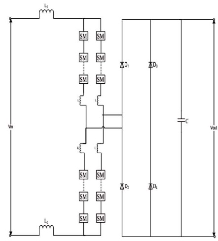
Figure 5. Unidirectional MMC DC-DC Converter
2.2 Isolated MMC DC-DC Converter In isolated MMC DC-DC converter, the AC sides of two voltage source converters is well adjusted and combined together by a means of AC transformer as shown in Figure 6. While correlating with the unidirectional converters, the structure used for the DC-AC-DC conversion accomplish and achieve the objective of bi-directional flow of power in isolated converters. This type of converters can isolate the DC failures by itself. The preference of selecting the single phase or ploy phase structure is totally dependent on the MMC transmission capacity and efficiency. The polyphase configuration is mainly employed for tremendous capacity transmission grid (Solas et al., 2013a).
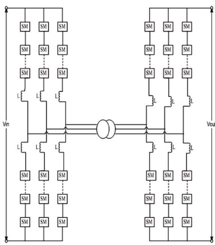
Figure 6. Isolated MMC-DC/DC Converter
The isolated MMC DC-DC converters can achieve high conversion ratio due to the presence of isolation transformer in it. It is mainly applicable for ground to HVDC transmission grid, where higher capacity and more number of high ratio converters are required. The main drawbacks of the isolated MMC based converters are higher core and operation losses with huge and bulky devices, which limits the advancement and expansion of the converter. Therefore it is not applicable for the offshore power generation as it demands for small volume equipments.
In the non-isolated MMC DC-DC converter shown in Figure 7, both the high and the low voltage DC system contribute to share the same bridge arm of the commutation part, thus it does not require any intermediate transformer as the isolated MMC DC-DC converter. These types of converter have various benefits, such as small size and weight of converter, reduced number of sub-modules, etc. The single phase non-isolated MMC DC-DC converter is mainly implemented for the situations, where it requires small capacity of transmission. The polyphase non-isolated MMC DC-DC converter is mainly implemented for the conditions, where large capacity of transmission is required. The HVDC transmission system utilizes various reactive power and constant DC control technologies. Due to the absence of the intermediate transformer, it is restricted to larger ratios. Thus it is mainly applicable for low ratio conditions such as interconnection between two HVDC grids whose voltage level does not differ largely from each other.
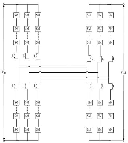
Figure 7. Non-Isolated MMC DC-DC Converter
In order to transmit the power, there is direct electrical interconnection between the low voltage and high voltage side of the MMC DC-DC autotransformer as shown in Figure 8, it is same as the primary and secondary side connection of the auto-transformer. Therefore it minimizes the converter capacity and decreases the operation losses. While comparing to the other traditional MMC based DC-DC converters, it can accumulate large capacity of Voltage Source Converter (VSC), uncontrolled rectifier, and AC magnetic networks.
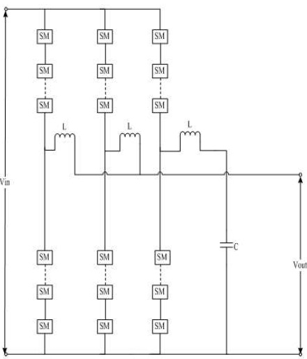
Figure 8. MMC DC-DC Autotransformer
The MMC DC-DC autotransformers are mainly known for their higher efficiency, reduced losses, and cheap cost. When the voltage conversion ration becomes too high, the efficiency of the energy conversion of the converter reduces; thus it is usually applicable for the areas with reduced ratio demands. The main drawback of these types of converters is that it cannot isolate the DC fault without using the DC breakers.
In order to develop and get better the future performance presentation of the converter and to accomplish higher utilization, the MMC base improved DC-DC converters are introduced. It is implemented with hybrid cascaded converter and is introduced with three phase parallel connection induced in it. Each single phase constitute of controlled switches and spread over a period of time in order to store energy for the buffer modules comprising of cascaded HB-SM. Every controlled switch consists of a series connected diode in anti-parallel with the IGBTs. The input and output voltage of the converter is totally dependent on the sub-modules in energy storage buffer modules and energy conversion attained by phase shift modulation. While comparing with the various MMC based DC-DC converters, the improved converters have many benefits, such as smaller volume, reduced switching losses, reduced device count, cheap cost, etc. It is mainly applicable transmission system such as HVDC systems that requires high conversion ratios.
Due to its structural modularity, the MMC can enhance an acceptance of fault tolerating by raising surplus submodules in its framework, thus improving reliability of the system. However, controlling the hardware restricts the precision and truthfulness of the converters away from some definite and assured greatest redundancy boundaries. In other words, any increment in number of surplus sub-modules higher than the upper limits may guide toward deteriorating the consistency of the converters.
It has been indicated in various studies that MMC have greater effectiveness of lager efficiencies as compared to the other multilevel structures. Primarily to organize and diminish losses it is feasible to regulate the internal current of the present elements. MMC losses can be evaluated using multiple techniques such as modification of switching waveform, calculation of semiconductor energy, and use of interpolations, real time waveform for the changing, and adjusting the model of switching losses. In perspective of the semiconductor, the power cells based on IGCT have reduced losses than that of the power cells based on IGBT. Subsequently, the NPT-IGBT and the SIC based semiconductor are assessed for the practicing in the cells of MMC and thus it has been discovered that the losses can be further reduced and the effectiveness of the efficiency can be rapidly enhanced.
The characteristic of the MMC is tolerating the fault failures owing to be the big amount of continues repetitions. Furthermore in addition, the control system can also be implemented in order to detect and encounter the failures in order to adjust and customize the given converter structure by decreasing the impact of the failures on the general operation and implementation of the converter. Because of this, converters enhanced present dynamics, the short circuit of the current restriction performance strategies can be introduced for the self handling and management of the DC errors or faults by the converter itself
The capacitors of each and every cell should be accused and charged to a significant value during normal operating range of the converter. On the other hand, owing to the converter elevated equivalent capacity and the charging method while starting the converter or after clearing the faults may produce very high inrush current. In order to remove and ignore arising of such problems, certain different pre-charging methods are designed and introduced during converter operation. The simplest one is using a resistor for a small span of time. The resistor will be linked in sequence with the converters. It is not adequate and energy efficient declaration and may also result in high voltage operation of huge and massive resistances. An alternative approach is made to hold the charging of capacitors in a staggered series to charge them at single moment. These alternative methods need no additional hardware, but have more complicated control system, and it should work even though the converter cells are entirely discharged. It is possible to apply and execute a mixture of the techniques together by minimizing the pre-charging of resistors and the control complications.
The relations connecting the arm current and the modulating signal leads to production of voltage ripple in capacitors. This relationship among the ripple voltages and circulating currents was fully researched in order to utilize the current to decrease the magnitude of ripple and its impact on the converter. The decreases in ripple have been discovered to have a finite variety of activity provided by the converters maximum largest circulating currents.
The foremost control intention of MMC is to control the terminal voltage and current. It may be necessary to have a command over the DC voltage and current according to the application of converter. The capacitor as an energy storing device of converter can act like energy crossing point connecting the input and output Deng & Chen, 2014). The voltage of capacitor must be adjusted or controlled in such a way that it gives a stable operation in steady state of converter. The secondary control goals like effect of the circulating current and equalization of the stress over the energy cell, reduced losses, etc., are also present. Thus the control of MMC can be split into various classes depending on various control goals and are as described below:
4.1.1 Control of Arm Current
The control of the arm current is a typical way of controlling the input and output voltage and current correspondingly (Son et al., 2012). Thus the converter configuration present in every arm is regulated by mixture of arm current and voltage. The fundamental presents a control approach implemented to MMC on the basis of the reference input and output for a specified point while calculating the modulating signal. It also needs compensation expression in order to ignore and diminish the steady state error (Ilves, Harnefors, Norrga, & Nee, 2015).
4.1.2 Control of Circulating Current
The MMC generates the circulating current, these are the inner current flowing between the arms of converter and not flowing outside of converter. The circulating current is generally second order negative sequence harmonic currents. At same time, if the circulating currents are not suppressed or controlled, it may boost up the RMS value of arm current, it may lead to unreasonable excessive power loss, leads the power factors towards unity, and also increases the amplitude of sub module (SM) voltage ripples (Mei, Shen, Xiao, Tolbert, & Zheng, 2013).
The capacitor voltage ripple is one of the sources of circulating currents in MMCs, where the frequencies of current are double of the output frequencies. Optionally, the device can decrease circulating current to reduce the losses of converter and thereby enhance its control. The autonomous and separate controllers are used to control the circulating current, which also helps to simplify the controller design (Oleschuk, Blaabjerg, & Bose, 2002).
4.1.3 Voltage Balancing of Capacitors
Same as the various different multilevel converter topologies, MMCs also require maintaining a balance of voltages around the sub module capacitors (Peng et al., 2016). Thus advancement in the features of MMC includes the capacitor voltage balancing in it. It is a method or approach in which the sub-module capacitor voltages are modified and regulated in advance before sorting. This method mainly includes the sub-modules whose capacitor voltage raises definite voltage restrictions, when the switching state of other sub-modules remains constant (Qin & Saeedifard, 2012). The capacitor voltage of the OFF state sub-module whose capacitor voltage exceeds the voltage constraints to boost and amplify their likelihood of being bypassed in the successive switching sequence are launched and thus multiplied by a maintenance factor.
Most probably the voltage balancing methods are depending on the PWM modulation techniques, in which the selection of the sub-module that must be switched ON at any instant of time totally depends on the capacitor voltages along with arm currents of the converter.
The various Pulse-Width Modulation (PWM) techniques, based on using a single reference waveform, that have been developed/proposed for the MMC include:
4.2 1 Phase Shift Carrier Based PWM Techniques
The Phase shifted carrier based PWM (PSC-PWM) technique can easily overcome all the lower order harmonics for the multilevel converters. On the other hand in the conventional PSC-PWM technique, each carrier correlates to the switching cycle of individual sub-modules. In this method, each of the MMC sub modules is individually and separately regulated. The MMC sub-module voltage balance task is split into two components, i.e. control average and balance control. Both the average and balance control functions are used to maintain the average sub-module capacitor voltages and balance the voltages of the specific sub-module capacitor, respectively. For an MMC with N sub modules per arm, the position arm voltage are compared with triangular carriers, each stage is being moved at an angle of 360/N. Evaluation of every sub-module voltage reference waveform with the triangular carrier produces a signal for switching operation of the sub-modules (Ren, Sun, & Xiao, 2017). This method of modulation is used for the MMCs, due to the following distinct features:
The execution and realization of PSC-PWM method constitute of the subsequent steps:
4.2.1.1 Level-Shifted Carrier Based PWM Techniques
This method is implemented for controlling the different multilevel power converter. In this method in the linear modulation region, the carrier signals with the same peak to peak level and frequencies are vertically inclined. Every carrier signal represents two voltage levels; therefore for this reason the name Level shifted. Based on the output voltage concentrations, this method is introduced and can be readily implemented to any multilevel converters. Therefore this modulation system is lesser preferable for MMCs as it creates unequal division and allotment of energy losses within the various sub-modules and equipments. It also impacts the harmonic distortion of AC output voltages, capacitor voltage equilibrium, resulting in uneven division of MMC voltage ripples of sub-module capacitors, and higher circulating currents.
4.2.1.2 Staircase Modulation Technique
In the staircase modulation technique, every leg of MMC is autonomously controlled using a staircase type modulation method. This technique generates the required reference stage voltages using the closest voltage levels, thus also known as Nearest Level Modulation (NLM). Primarily it ignores or avoids the use of triangular signal and mainly focuses on switching frequencies and its modulation. The switching states and dwelling times is calculated straightly since the reference of phase voltages. This system is simple to execute in digital controller and for higher power MMC based HVDC devices it is most realistic and convenient PWM techniques. If there are fewer sub-modules per arm, the NLM technique produces bad feature of voltage waveform. The staircase modulation technique is therefore primarily used for higher voltage applications, where the amount of steps is very high, i.e. up to 100-200 steps or above.
The DC-DC converters have efficiently, highly developed into the industries, and hence can be explained as a fully developed and established technology. Since HVDC is appearing as the best solution for long distance power transmission with significant reduction in losses and lower charge of expenditure. A modular multilevel DC-DC converter has become new promising, outstanding, and most commonly used components for the HVDC transmission as it fulfills all the characteristic requirements of the HVDC transmission. This paper is devoted to a review on Modular Multilevel DC-DC converter with various SM structures and different types of MMC based DC-DC converters. It also explains the appropriate utilization of different types of control and modulation methods for various categories of MMC based DC-DC converters.