Figure 1. Circuit Diagram for 9 V Output
The cost of fuel is getting increased and the effect of gases being emitted from the burnt fuel is weakening the ozone layer. Carbon emission has also become a big challenge in today's world. Therefore, by using solar power, we can reduce carbon footprints. Lawn mowers are becoming popular now-a-days. Grass cutting being a tedious work for human beings, can be simplified by using an automatic grass cutter, which can be performed without a physical person being present. While cutting the grass, there are some obstacles, which obstruct the cutting of grass and sometimes the blades of the machine get damaged, so it is necessary to avoid obstacles. For that we have to identify the obstacles first and then we have to change the path of the lawn mower. Supplying power to the lawn mower is a big issue while designing the model. In this paper, the authors have used a solar panel to charge the battery and the power stored in the battery is utilized to power the electric motors, which will rotate the blades to cut the grass.
A lawn mower is a device which can cut the grass in the lawn evenly. An obstacle avoiding lawn mower can cut the grass without hitting the obstacles in front of it. That means it can avoid the obstacles and change the path. Dipin and Chandrasekhar (2014) developed a vision based lawn mower, which can detect the objects by an ultrasonic sensor. Satwik, Rao, and Reddy (2015) have designed and developed lever operated solar lawn mower and have done the contact stress analysis of spur gears. Nourani-Vatani, Bosse, Roberts, and Dunbabin (2006) have prepared a tractor lawn moving vehicle, which can cut the long grass autonomously by using Atlas Framework with Rapidly-Exploring Random Trees path planning and Virtual Force Field obstacle avoidance. An obstacle avoiding robot was developed by Kumar et al. (2013), which used an infrared sensor to detect the objects in front of the robot and coded a program in the microcontroller to drive the two motors such that the robot can change the path.
Nasucha (2015) developed an obstacle avoiding robot, which can detect the objects by using a proximity sensor. He has written the program in the microcontroller to control the movement of robot. He prepared this towards a bigger goal of development of an autonomous vehicle. Dutta, Baruah, Konwar, and Kumar (2016) have compared different technologies for making efficient and low cost lawn mowers such as, solar powered lawn mower, automatic lawn mowers, gas powered lawn mowers. Hicks and Hall (2000) have presented a brief survey of available robotic lawn mowers, their patents, and some prototypes. They also suggested some of the technologies which could increase their capability. A low cost portable lawn mower was developed by Sivagurunathan, and Hao (2017). They have taken strength, durability, and weight as the design considerations for better performance. Solar grass cutter with linear blades by using scotch yoke mechanism was developed by Amrutesh, Sagar, and Venu (2014). They have used a panel and the power from the solar panel is stored in the battery. They used this power to run the motors, which have blades so that they can cut the grass. Here they have used scotch mechanism which is also called as slotted link mechanism, where the conversion of linear motion of slider into rotational motion takes place and vice versa. Okafor (2013) designed a self power lawn mower with a list mechanism to alter the height of the cut.
In this paper, the authors have used an Arduino that will control the movement of wheels and blades. An ultrasonic sensor is used to detect the obstacles in front of it.
Arduino Uno is a circuit board that contains all the necessary ports to connect a microcontroller. It has 14 pins, out of which one is supply, one is ground, 6 are used for PWM outputs, and 6 are used for analog inputs. It also has a USB connection port, a power jack port, 16 MHz ceramic resonator, an ICSP header, and a reset button. To power this board, it must be connected to a computer with a USB cable or an AC to DC adapter is connected from the supply board.
There are different types of Arduino boards available, Arduino Uno is the latest version of all the boards. It has a special feature that it can be programmed as a USB to serial converter.
Arduino Uno can be programmed with the downloaded Arduino software. Select Arduino Uno from the Tools > Board menu (according to the microcontroller on the board).
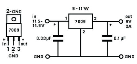
The solar panel is connected to the battery and the voltage from the battery is regulated to 9 V by using 7809 regulator and is given to the Arduino. The circuit diagram for the 9 V output is shown in Figure 1.
Figure 1. Circuit Diagram for 9 V Output
The 7809 is a voltage regulator that restricts the voltage output to 9 V. This circuit protects from overvoltage and short circuit.
The Ultrasonic distance sensor (shown in Figure 2) provides precise, non-contact distance measurements from about 2 cm to 3 meters. It is very easy to connect to Microcontrollers, propeller chip, or Arduino, requiring only one I/O pin.
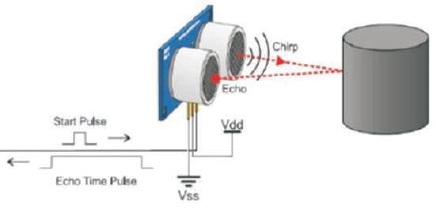
Figure 2. Ultrasonic Sensor
The sensor has 3 pins, out of which first pin is connected to ground, second pin is connected to 5 V supply, and third pin is a signal pin, which is connected to microcontroller. When an object is detected, the sensor detects and sends the signal to the microcontroller through the third pin.
It has two main parts, one is emitter and the other is receiver. When supply is given to the sensor, the emitter emits a 40 KHz ultrasonic burst continuously. When this burst touches an object and reflects back, the receiver receives that echo and sends a signal to the microcontroller through the third pin.
The block diagram of the proposed lawn mower is shown in Figure 3.
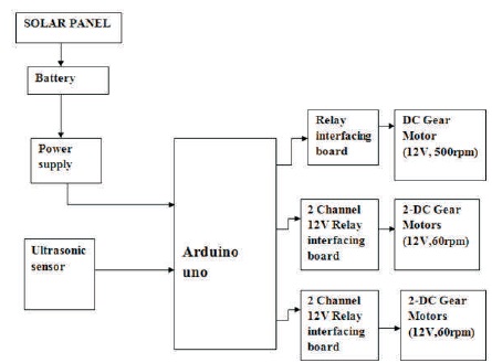
Figure 3. Block Diagram of the Proposed Lawn Mower
The lawn mower has a panel arrangement in such a way that it can receive solar radiation with high intensity easily from the sun. The solar panel converts solar energy into electrical energy. The solar lawn mower will be moved over a grass land to cut the grass in the lawn. When the switch is closed, the Arduino sends signals to the relay to switch ON the motors and the motors start rotating in the forward direction. The Arduino also sends signal to the relay connected motor to which the blade is attached, where the blades rotating in high speed cuts the grass. We can adjust the level of blade for different levels of grass cutting. Whenever, any obstacle is detected by the sensor, then the Arduino sends a signal to the relays connected to the motors (driving purpose) in such a manner that the motors in left side of lawn mower rotates in forward direction and motors in right side of the lawn mower do not rotate so that the lawn mower moves towards its right until the obstacle is overcome by the lawn mower. Again the lawn mower moves forward continuously and cuts the grass.
Relay 1 operates the right wheel in the front side, relay 2 operates the left wheel in the front side, relay 3 operates the right wheel in the backside, relay 4 operates the left wheel in the back side, and relay 5 operates the blade.
The hardware implementation of the proposed lawn mower is shown in Figure 4.
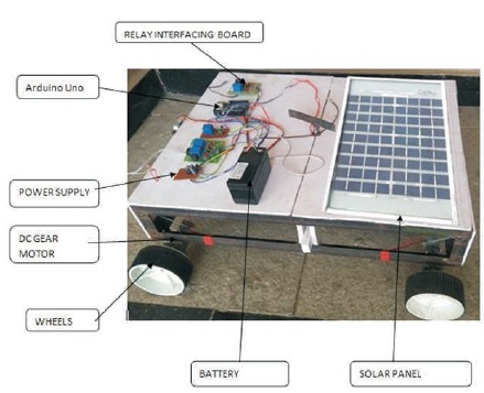
Figure 4. Model of a Lawn Mower
The basic connections in the hardware are given below.
The terminals of solar panel are connected to battery. The battery terminals are connected to power circuit board. The output of power circuit board is given to Arduino through a voltage regulator 7809 to reduce the given input voltage from 12 V to 9 V to Vcc pin. So the Arduino receives 9 V power. The ultrasonic sensor is connected to the digital input pin (8,9) of Arduino. The relays 1, 2, 3, 4, 5 are connected to pins 2, 3, 4, 5, 6 of Arduino, respectively. The motors 1, 2 are connected in parallel and given to pins of relay 1, 2. The motors 3, 4 are connected in parallel and given to pins of relay 3, 4. The motor used for cutting purpose is given to pin of relay 5. Supply to relays is given by the Vcc terminal in it.
The obstacle avoiding lawn mower was build, tested, and run successfully. As a solar panel is used, carbon emissions were reduced and there is no fuel cost and manpower required. The DC motor used is operated in low power with high efficiency. The battery is charged by the solar panel in a constant voltage. This product eliminates the physical power required in pushing the mower without compromising safety.
The program which is written to drive the motors and blade is given below.
int relay1 = 2;
int relay2 = 3;
int relay3 = 4;
int relay4 = 5;
int relay5 = 6;
int trigPin1 = 8;
int echoPin1 = 9;
void setup()
{
Serial.begin (9600); pinMode(trigPin1, OUTPUT); pinMode(echoPin1, INPUT); pinMode(relay1, OUTPUT); pinMode(relay2, OUTPUT); pinMode(relay3, OUTPUT); pinMode(relay4, OUTPUT); pinMode(relay5, OUTPUT);
}
void loop()
{
digitalWrite (relay5, HIGH);
int duration1, distance1;
digitalWrite (trigPin1, HIGH); delayMicroseconds(5);
digitalWrite (trigPin1, LOW);
duration1 = pulseIn(echoPin1, HIGH); distance1 = (duration1/2) / 29.1; if(distance1<1)
distance1=0;
Serial.print("DISTANCE:"); Serial.print(distance1);
Serial.print("cm ");
Serial.println();
delay(500);
if(distance1 > 0 && distance1 <= 50)
{
digitalWrite (relay1, LOW);
digitalWrite (relay2, HIGH);
digitalWrite (relay3, LOW);
digitalWrite (relay4, HIGH); delay(1000);
digitalWrite (relay1, HIGH);
digitalWrite (relay2,LOW);
digitalWrite (relay3, LOW);
digitalWrite (relay4, HIGH); delay(3000);
digitalWrite (relay1, HIGH);
digitalWrite (relay2, LOW); digitalWrite (relay3, HIGH);
digitalWrite (relay4, LOW);delay(2000);
}
else
{
digitalWrite (relay1, HIGH);
digitalWrite (relay2, LOW);
digitalWrite (relay3, HIGH);
digitalWrite (relay4, LOW);
}
}