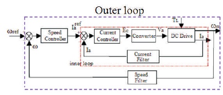
Figure 1. Block Diagram of Power Converter fed DC Drive with Double Loop Control
The speed control of the DC drive in industry is very important for product of quality goods. This paper deals with a mathematical model of DC drive fed with different converters and the design of the double loop control structure for its speed control. In double loop control structure, the proportional and integral gains of speed controller are evaluated using Ziegler Nichol’s open loop (S-curve) and Symmetrical Optimization methods. The performance of DC drive using the double loop control is analyzed using MATLAB/ Simulink. The simulation results with constant operating speed, indicate that the DC drive using the double loop control designed with Symmetrical Optimization method provides the superior speed performance than the DC drive using the double loop control designed with Ziegler Nichol’s open loop method. The similar speed response can be obtained with the selected PI gains of double loop control for variable speeds. Finally, a comparative study has been done to highlight the benefits of the double loop control, which is made with Symmetrical Optimization than Ziegler Nichol’s open loop method.
The main backbone of most industrial applications and electric traction is DC drives because of their simple construction, lower cost, efficiency, and good reliability (Monfared et al., 2015). Since DC motors have excellent speed control characteristics for acceleration and retardation, they are in variable speed/load applications. Furthermore, the fact that the power supply of a DC motor connects directly to the motor field allows for precise voltage control and assists speed and torque control applications. In this context, to achieve the desired speed, the DC drive speed is controlled while varying either armature voltage or field flux. Thereby, research studies reveal that there have been many varieties of control schemes and lots of applications for speed control of DC motor drives such as a conventional armature control method for low power DC motor drives, conventional PID controller, fuzzy logic technique, constant power motor field weakening controller based for high speeds. In recent years, most of researchers focused on simplifying the classical model structure by transforming the inner loop to a reduced form using various model reduction techniques. These various works provide a significant improvement in the DC drive speed performance by overcoming some practical problems (Guedri & Chaari, 2015; Miková, et al., 2016; Haishui et al., 2010; González-Rivera, et al., 2011; Khan et al., 2015).
In this paper, the symmetric optimization strategy is proposed to design a double loop control structure for speed control of DC drive fed with various converters. The speed performance using proposed method was compared with classical Ziegler – Nichol’s open loop method in MATLAB/Simulink environment.
The symmetric optimization method is easier to understand than other advanced control methods. Using this method, the gains of PI controller is obtained by developing the mathematical model of DC drive. This controller can be easily implemented for real-time applications of keeping motor speed at any desired set-point speed under varying operating conditions. Figure 1 shows the schematic diagram of power converter fed DC drive fed with double loop control structure.
Figure 1. Block Diagram of Power Converter fed DC Drive with Double Loop Control
This research describes the double loop control structure of power converter fed DC drive by keeping the field flux constant. The inner and outer loops are main loops of the double loop control structure of DC drive (Figure 1). The inner loop is a current loop that compares the armature current (Ia) with reference armature current (Iaref). The difference Ia -Iaref is called current error; it is fed to the current controller. Similarly the outer loop, also called as speed loop, generates the speed error by comparing the output signal from speed filter (ω) with speed reference (ωref) and this speed error signal (ω-ωref) is fed to speed controller. The output of current controller is fed to converter for its proper operation (or for duty control when a chopper is used) (Guedri & Chaari, 2015; Rajasekhar et al., 2013).
Figure 2 shows the schematic diagram of two quadrant 3- Ph converter fed DC drive (Bimal, 2001).
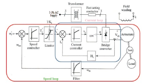
Figure 2. Two Quadrant 3-Ph Converter-fed DC Drive
The converter receives AC supply through a 3-Ph transformer and its DC output is fed to armature of DC drive. In this research, the field of the DC drive is excited by a separate constant DC source. For closing the speed loop, the DC drive has a tacho-generator. The DC drive is running with a load. The output the tacho-generator is filtered to remove the ripples to provide a speed signal ωmr with the help of speed filter. The speed command ωr* is compared with speed signal ωmr to generate a speed error. This speed error signal is processed through the PI speed controller to determine the torque command. To keep the torque in safe current limit, the torque command is limited using limiter. Now the armature current command Ia* is compared with armature current Ia to generate a current error. This error is applied to the PI current controller to produce control signal Vc. This control signal modifies the trigger angle α of the converter.
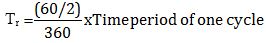
The two quadrant converter is modeled with its gain Kr and time delay Tr as time period of one cycle.
Here the gain of the converter for maximum control voltage Vcm is given as Kr = 1.35Vac /Vcm. The sampling interval of converter gives its time delay because the converter is a sampled data system. When a two quadrant controlled converter is used for good operation of thyristors, the delay angle interval should be within 600 . Now the delay time of converter is evaluated by treating the angle delay as half of this interval, i.e
The chopper is modeled as first order lag function with gain Kr , delay time T is average conduction time. If Vs is DC link voltage, Chopper gain Kr =Vs/Vcm.
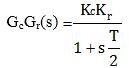
Here Kc is the gain of the PWM current control, Kr is the gain of the chopper and time constant T is given by Krishnan (2001). In practice, the PWM current control is modeled as a unity gain block with negligible time delay.
Due to the back emf, the DC drive contains an inner loop called inner current loop (Livinti & Livint, 2005). The modeling of DC drive is complex because the inner current loop crosses the back emf loop as shown in Figure 3 (Bimal, 2001; Krishnan, 2001; Verma et al., 2012).
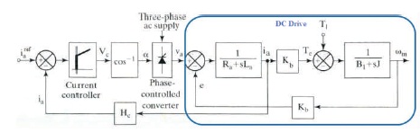
Figure 3. DC Drive with Inner Current Loop
The interactions of these loops are decoupled and redrawn as shown in the block diagram in Figure 4. The main assumption is that the load is proportional to speed, i.e TL = BL ωm .
The overall transfer function of DC drive is obtained by splitting the transfer function between speed and armature voltage as a transfer function between speed-armature current and transfer function between armature current and armature voltage (Krishnan, 2001; Ramesh et al., 2010; Wang et al., 2013; Kiruthika et al., 2013).
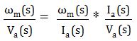
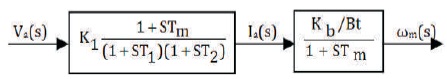
Figure 4. Overall Transfer Function Block Diagram
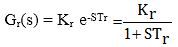
To regulate the motor speed automatically, a controlled variable is necessary. This controlled variable is measured with the Tacho-Generator. To filter out the ripple in measured speed, a feedback speed filter is used in Xuan and Sheng (2010). The transfer function of a speed feedback filter is given as,
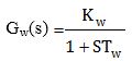
Kw , Tw are the gain, time constants, respectively.
Hc is the gain of the current feedback. Practically, the c current feedback does not require a filter. A low-pass filter is used when the filter is required. The current feedback gain Hc = 7.07V/Imax .
Figure 5 shows the block diagram of the current control loop. The loop gain is given as follows.
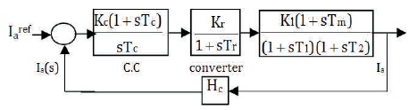
Figure 5. Transfer Function Model of DC Drive with Inner Current Loop
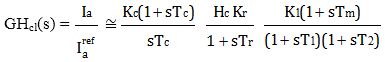
Equation (7) indicates 4th order system transfer function. To synthesize a current controller, the above equation is simplified to the 2nd order system by some approximations, i.e 1+sTm ≅ sTm , the time constants in denominator have the relationship Tr < T1 < T2 and selecting the current controller time Tc as T2 . Equation (7) can be written as (Krishnan, 2001; Bajracharya et al., 2008; Ramesh et al., 2010).
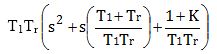
The characteristic equation of above transfer function is (1+sT1 )(1+sTr). The standard form of this equation is as follows.
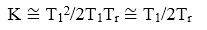
From the above equation, natural frequency and damping ratio are,
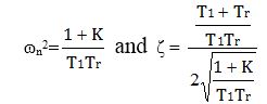
For good performance, the damping ratio, practically, should be 0.707. Now from equation (10)
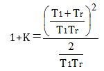
Since T1 >> Tr and K >> 1, equation (9) can be written as,
From equations (8) and (12), the current controller gain is
Kc = T1Tc/2TrK1KrHcTm.
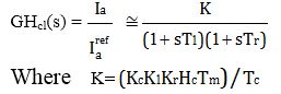
The speed loop with current control loop is shown in Figure 6 (Guedri & Chaari, 2015). The transfer function between output signal of speed filter for reference speed is GHs(s).
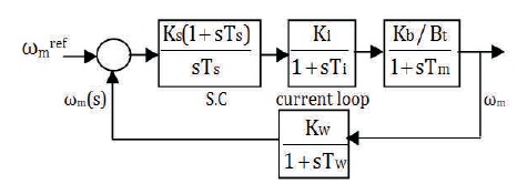
Figure 6. Transfer Function Model of DC Drive with Inner Current Loop
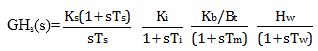
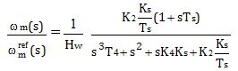
The above equation indicates 4th order system transfer function. For analytical design of speed controller, the order of the above equation is reduced with some approximations. The first approximation is 1+sTm ≅ sTm. The next approximation is the equivalent sum of time delay of speed filter (Tw) and current loop (Ti) is very much less than integrator time constant Ts , i.e equivalent time delay T4 = Ti + Tw. Hence the speed loop gain function is,
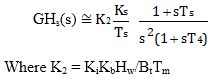
Now,
A controller produces an error signal e(t) continuously as the difference between a desired set point and a measured variable and it generates a control signal u(t). The controller attempts to minimize the error signal e(t) over time by adjusting the control signal u(t) to a new value. Since the PID controller depends only on the measured variable y(t), it is broadly applicable. The response of the controller can be described in terms of its responsiveness to an error e(t), the degree to which the system over-shoots a set-point and the degree of any system oscillation (Ogata & Yang, 2002).
A PID controller is called a PI, PD, P, or I controller in the absence of the respective control actions. PI controllers are fairly common, since derivative action is sensitive to measurement noise, whereas the absence of an integral term may prevent the system from reaching its target value. There are number of methods available for tuning of PI controller (Rashid, 1993; Visioli & Vilanova, 2012). In this research paper, for tuning of PI speed controller, Ziegler-Nichol’s open loop method and symmetrical optimum criterion are used.
The overall closed loop system of power converter fed DC drive is shown in Figure 7.
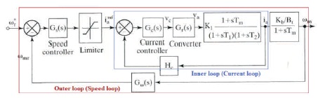
Figure 7. Overall Closed Loop System of DC Drive
The Ziegler-Nichol’s tuning of controller is very popularly used in real time process control systems. The coefficients of the PID controller can be obtained as follows. The output response of the open loop system of the plant for the unit step input is shown in Figure 8 (Krishnan, 2001).
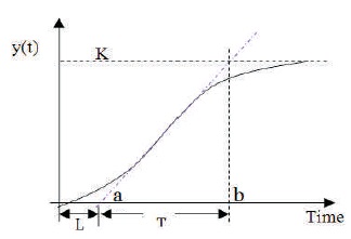
Figure 8. Open Loop Response (S curve)
From the output time response, the gain constant k, delay time L, and time constant T are measured. Here the delay time L is measured from origin to 'a', where the tangent line cuts the time axis as shown in Figure 8. The time constant T is measured between the points 'a' and 'b' on xaxis. The coefficients of controller are determined as,

A symmetrical optimum design criterion obtains a controller that forces the frequency response of the system as close as possible to that for low frequencies. The method has the advantage of maximizing the phase margin. As phase margin is maximized for given frequency, the system can tolerate more delays, which is important for systems having delays. This method optimizes the control system behavior with respect to disturbance input (Bajracharya et al., 2008). The method has well established tuning rules and has good disturbance rejection (Aydin et al., 2005).
The gain values of speed controller are obtained by minimizing equation (15) using symmetrical optimization conditions (Ramesh et al., 2010). From equation (15), Let
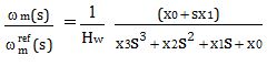
Here x0 =K2 Ks /Ts , x1 =K2 Ks , x2 = 1, and x3 = T4 .
The above transfer function is optimized for maximum bandwidth (Bajracharya et al., 2008). The magnitude of the above equation is
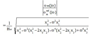
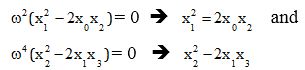
Substituting these conditions, the speed controller gain Ks = 1/2K2 T4 and time constant Ts = 4T4 .
The MATLAB/Simulink results of different converter fed DC drive with double loop control structure have been obtained for various speed conditions. Firstly, the simulation results have been obtained for constant reference speed of 1235 rpm (i.e 196.55 rad/s), then for variable reference speed (for variable load applications) i.e the drive has to run with 850 rpm for 0 to 0.25 s, 500 rpm for 0.25 s to 0.75 s, and 1235 rpm for >0.75 s. In this context, simulation has been performed upto t=0.8 s.
The Figure 9(a) shows the motor speed (i.e output signal of speed filter) with respect to time. With Ziegler-Nichol’s method, the peak overshoot is 12% and settling time is 71.02% more than peak overshot and settling time with symmetrical optimization method, respectively.
Figures 9(b) and 9(c) show the speed error in r.p.m and current error in Amps.
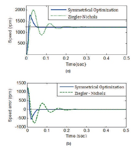
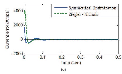
Figure 9(a) Speed vs. Time (b) Speed Error vs. Time ( c) Current Error vs. Time
Practically, the speed of the drive depends on its load, i.e when the load on the drive changes, its speed also changes. In this case, speed performances using PI speed controller with various tuning methods are compared when a sudden load is added at different time intervals.
From the speed response in Figure 10(a), when the load is enhanced, Ziegler – Nichol’s tuned PI Speed controller along with the current controller provides a small peak overshoot and recover y time than symmetrical Optimization PI Speed controller. But both controllers provide the perfect speed tracking with zero steady state error. Figures 10(b) and 10(c) indicate speed and armature current error responses with varying load conditions.
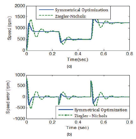
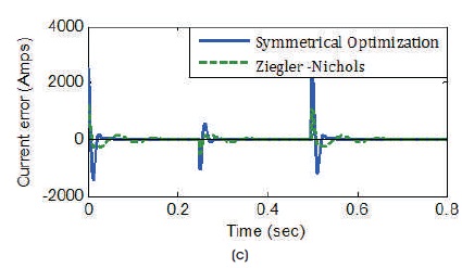
Figure 10(a) Speed vs. Time (b) Speed Error vs. Time ( c) Current Error vs. Time
Figure 11(a) shows the motor speed (i.e Speed output signal of speed filter) with respect to time. With Ziegler- Nichols open loop method, the peak overshoot is 14.83% and settling time is 51.40% more than peak overshoot and settling time with Symmetric Optimization method, respectively. Figure 11(b) shows the speed error in r.p.m. Figure 11(c) shows the current error in Amps.
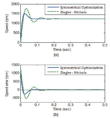
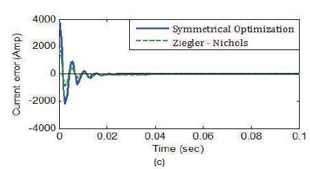
Figure 11(a) Speed vs. Time (b) Speed Error vs. Time ( c) Current Error vs. Time
From the speed response in Figure 12(a), when the load is enhanced, Ziegler – Nichols tuned PI Speed controller along with the current controller provides a small peak overshoot and recover y time than symmetrical Optimization PI Speed controller. But both controllers provide the perfect speed tracking with zero steady state error. Figures 12(b) and 12(c) indicate speed and armature current error responses with varying load conditions.
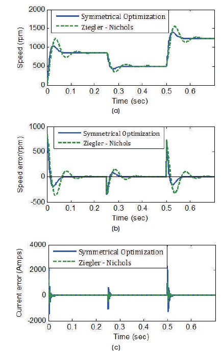
Figure 12(a) Speed vs. Time (b)Speed Error vs. Time ( c) Current Error vs. Time
Tables 1 - 3 show the comparative study of speed performance of DC drive fed with two quadrant and chopper using double loop control structure. Table 3 clearly indicates that the speed performance of chopper converter fed DC drive with double loop control is very superior than the speed performance of two quadrant converter fed DC drive.
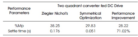
Table 1. Performance of Two Quadrant Converter Fed DC Drive
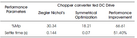
Table 2. Performance of Chopper converter fed DC drive
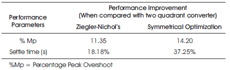
Table 3. Performance Improvement
In this work, the mathematical modeling of DC drive transfer function, design of double loop control (i.e inner current loop and outer speed loop controllers) were explained clearly. For constant and variable operating speeds, the DC drive using the double loop control designed by symmetrical optimization provides better speed performance and stability compared to double loop control Ziegler – Nichol’s method. It is shown graphically that there is a better enhancement in the time domain specification in terms of lower rise time (tr), settling r time (ts), and peak overshoot (% Mp).
Also, with the simulation results, the DC drive fed with chopper converter provides superior speed response than the speed response of two quadrant fed DC drive.
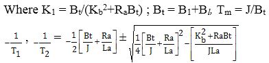
The parameters of the DC drive (Table 4) for this research are obtained from R & D cell, Power Electronics and Drives, Annamacharya Institute of Technology and Science (Autonomous), India.
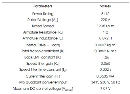
Table 4. Parameters of DC Drive with Double Loop Control
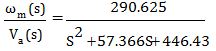
From equation (4), the time constants T1 = 0.1077 s, T2 = 0.0208 s, and Tm = 0.7 s.
Transfer function of DC drive:
Transfer function,
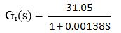
Transfer function of Converter:
The two quadrant converter converts AC supply into DC and this DC is fed to armature of drive. The model of this converter is given as,
The chopper is modeled as first order lag function as,
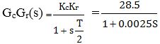
where Kc = PWM current control gain = 1, Kr = 28.5, and Delay time T = 1/2000 = 0.0005 s.
Tables 5 and 6 show the gains of PI speed and current controllers using Ziegler-Nichols and symmetrical optimization methods, respectively.
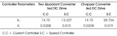
Table 5. Gains of PI Speed and Current Controller using Ziegler Nichols Method

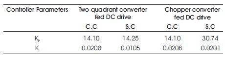
Table 6. Gains of PI Speed and Current Controller using Symmetrical Optimization Method