
Figure 1. Block diagram of PM BLDC Motor
In this paper, the authors report the generation of gating pulses for Voltage Source Inverter using microcontroller to drive PMBLDC motor. Gating pulse generation takes places with the help of emulated hall sensor output. These Hall sensor signals produced by the microcontroller remain high for 180o electrical angle. It remains low for next 180o electrical angle. The Hall sensor output shows a phase shift of 120o in each signal. Designated algorithm exhibits that frequency of gating pulses strongly depend upon the frequency of emulated Hall sensor. The present study can provide significant information in the analysis of Voltage Source Inverter without connecting the PMBLDC motor. Effectiveness of the proposed method are validated and proved by experimental data.
Over few decades, a research on automobile industry is highly focused on Electric Vehicle (EV) and Hybrid Electric Vehicles (HEVs) Technology for traction in short distances, which are generally passenger vehicles (Tashakori et al., 2010). Energy issues, such as charging, charge retention, and conventional drive technology limits the use of EV and HEV. Several methodologies have been employed to increase efficiency as well as low charging time of power sources, such as battery, fuel cells, etc. After the advent of high energy density, permanent magnets and sophisticated switching scheme for inverter, PM BLDC motors became a superior choice for traction. PM BLDC motor offers several advantages over brushed DC motors and induction motor, such as high torque to weight ratio, more torque per watt over all increased efficiency (Tibor et al., 2011), increased reliability, less noise and extended lifetime due to no brush, and commutator erosion. At the same time, it also shows significant reduction in Electro Magnetic Interference (EMI) and elimination of ionization spark from commutator. PMBLDC is a synchronous motor. Generally, the stator of a PMBLDC motor is similar to that of an induction machine, but the windings are distributed quite different. A distributed winding has a trapezoidal back EMF with a flat portion and in order to get constant power and low ripple output torque, this flat portion of back EMF is preferably fed with rectangular shape current (Sathyan et al., 2009). Rotor of PMBLDC motor is quite different than conventional motor. Unlike the DC motor which contains an Electromagnet, PMBLDC motor consists of permanent magnet which acts as a rotor. PMBLDC motor uses electronic commutation for VSI (Voltage Source Inverter). It involves sequential energizing windings which require the information about rotor position. Digital rotor position sensors and sensorless methods are generally used to determine the rotor position. The sensorless methods (Paul and George, 2011) are based on the back EMF of motor, which is trapezoidal in shape and have flat top. Back EMF is continuously monitored in the sensorless method. By sensing back EMF, rotor position could be determined. However, this method is not highly efficient (Wu et al., 2016). At low speed, it faces difficulties to sense the back EMF. Therefore it requires a starting algorithm in order to speed up the motor so that it can sense the back EMF (Gamazo-Real et al., 2010). The motor is driven by using Hall sensors that detects the position of rotor. Three Hall Effect sensors mounted on the stator of PM BLDC motor is displaced through 120o (Tabarraee et al., 2012).
When the rotor spins inside the motor, either the North or South Pole faces the Hall Effect sensors. As an effect, the induced voltage will appear across the sensor. This induced voltage signal gives information about the position of rotor. The position of rotor plays an important role in deciding the switching state of VSI. The position of rotor is continuously monitored by Hall sensors, which are used to energize the stator coil of PMBLDC through VSI. VSI act as a bridge between DC supply and motor in a traction system. Switching of VSI depends upon the rotor position and stator coil is energized in such a way that it shifts the rotor to next position.
Efforts have been made by various groups for the control of PMBLDC motor. However, it suffers some drawbacks during analysis of voltage or gate pulse of VSI in case of poor quality sensor or failure of any one of the Hall sensors. Hence a detailed investigation has been carried out in this paper for digital control of PMBLDC motor, which is cost effective and provides ease of implementation. In this present paper, the authors report the generation of Hall Sensor output through a microcontroller. This generated Hall sensor output has been used to generate the corresponding gating pulses for VSI. The gating pulses for VSI have been tested at different frequency without connecting the actual BLDC motor. There is also provision to modify the frequency of emulated Hall Effect sensor, which has been pointed towards to the rotor speed of BLDC motor. Generated Hall sensor output is nearly in perfect shape and frequency. Hence, gating pulses for inverter and inverter voltage is not affected by faulty or poor quality Hall sensors.
The block diagram of PMBLDC drive is shown in Figure 1. PMBLDC motor makes use of 120o mode of conduction of VSI and commutation angel is 60o for each switch of VSI. Power Electronic devices play a vital role in controlling the stator current supply, which is provided to PMBLDC motor by adopting different firing schemes for VSI, VSI is a link between DC supply and BLDC motor.
Figure 1. Block diagram of PM BLDC Motor
Voltage Source Inverter is shown in Figure 2. The output of VSI can be controlled through adopting different firing scheme, which eventually controls the output of BLDC motor. There are different techniques available to control the output voltage of VSI. It can be controlled through modulation techniques or by changing the DC link voltage.

Figure 2. Three Phase Voltage Source Inverter
The operation of VSI entirely depends upon the Rotor position. In sensored based control, Hall sensor provides information about rotor position and its output has 50 % duty cycle and each sensor output has 120o phase difference. Frequency of sensor output depends upon the speed of rotor. Hall Effect sensors detect the rotor position and drives the motor. BLDC needs to identify the rotor position data and makes the right commutation. Different techniques have been employed in past to detect the rotor position and generate corresponding gating pulses for VSI. Rotor position determination and corresponding gating pulse generation is a complex process. In case of sensored based control, gating pulses generation for VSI can be affected in case of failure of sensor or due to poor quality sensor. Generation of Hall sensor output by microcontroller reduces the complexity as it gives ease of testability of gating pulses as well as inverter voltage. Test can be performed without connecting the whole setup, which is BLDC motor and driving circuit for IGBT. By changing the pulses width of PWM pulses average voltage of VSI can also be changed, which results is change in speed. Hysteresis and PWM techniques are most widely used for speed control of PMBLDC motor (Tashakori and Ektesabi, 2012). Adjusting the DC link voltage can also be used to change the voltage, which results is change in speed. DC link voltage adjustment is considered in this work and PWM technique could be used to adjust the DC link voltage.
For the control of PMBLDC, Hall sensor provides useful rotor position data to operate VSI. Hall Sensor output has 50% duty cycle. Three Hall sensor states and corresponding switching states of VSI switches are tabulated in Table 1.
Two microcontrollers have been used to generate Hall sensor output and its corresponding gating pulses. Hall Sensor output is generated through applying logic pattern (either ON of OFF) as in Table 1 and corresponding switching patterns are generated through a well defined algorithm.

Table 1. ON State of switch in VSI and Hall Sensor state
Figure 3 shows Arduino boards and PC based Oscilloscope. There are three Hall Sensor signals, one for each phase designated A, B, and C. Emulated Hall Sensor outputs are shown in Figure 4 and 5. Emulated Hall Effect sensor outputs are produced by Atmel Atmega328p microcontroller.

Figure 3. Setup to generate Hall Sensor output and gating pulses for VSI

Figure 4. Hall Sensor A and B

Figure 5. Hall Sensor B and C
Hall sensor signals remain HIGH for 180o electrical angles and LOW for next 180 electrical angles (Tashakori et al., 2015) possessing duty cycle of 50 percent. There is phase shift of 120o in each phase (A, B, C). Duty cycle is kept fixed and frequency changes according to rotor speed of BLDC motor. For a reference to rotor speed, potential divider is used to set the speed reference to microcontroller. As we change the frequency of dummy Hall Effect sensor, the output switching pulses also changes its frequency accordingly. Hence in later stage, there is a provision to replace dummy Hall sensor as shown in Figures 4 and 5 with actual Hall Effect sensor outputs. By adopting this technique, any error during generation of switching pattern and voltage of VSI could be avoided due to poor quality sensor or faulty Hall Effect sensor. DC link voltage control or modulation technique could be used to adjust output voltage of VSI, which eventually changes the output of motor.
Figures 6 and 7 show experimental results obtained from the setup, which shows the gating pulses for Voltage Source Inverter for switch Q1, Q2, and Q3. In Figure 7, gating pulse for Q3 is show with respect to Q1. Similarly gating pulses for all semiconductor switches have been produced. An algorithm is designed to read the state of Hall sensor. These gating pulses are produced by a microcontroller that senses the incoming signal, which is Hall sensor’s output and produces these gating pulses.

Figure 6. Gate pulse for Q1 and Q2
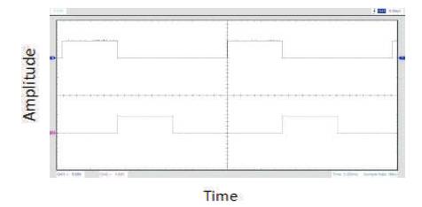
Figure 7. Gate pulse for Q1 and Q3
Based upon this dummy Hall Effect sensor’s output, switching pulses are generated with the help of a Microcontroller, and frequency of this gating depends upon the frequency of Hall effect sensor signal frequency, where this frequency is dependent on spinning speed of the rotor. So there is a provision to change the frequency through a potentiometer.
Microcontroller based Hall sensor output generation and gate pulse generation have been validated in this work. It is viable to implement the control algorithm with Atmel Atmega 328p microcontroller and at the same time, operating frequency is limited to a specific range. So in later stage, a powerful same algorithm could be implemented with powerful microcontroller for more smooth operation. The overall approach is low cost and performs easy analysis of the inverter. Instead of DC link voltage control, upper/lower switch modulation could be adopted to control the speed of PMBLDC motor.