(1)

It has been well established that light emitting diode shall invariably replace incandescent lamps and compact fluorescent lamps in smart cities. However one important aspect that needs to be addressed in the context of light emitting diodes and dimming is degradation of Correlated Colour Temperature (CCT). Dimming will alter the temperature at the junction and T-point. Thus any changes in light intensity will finally bring changes in the temperature. Subsequently with changes in T-point temperature CCT also changes. The degradation of CCT will implicate the quality and quantity of light delivered by LED. In LEDs apart from ambient temperature test point or commonly referred as T-point temperature also plays a vital role as it depicts the solder point temperature of the device. In this paper, an attempt has been made to work out a relation between the T-point temperature and CCT. This relation will provide sufficient insight to the manufacturers. Furthermore, the aspect of quality lighting is also required to be dealt in smart lighting. This work primarily offers substantive information regarding the change in CCT with corresponding changes in T-point and ambient temperature.
The impact of smart cities has opened up a new dimension of understanding lighting applications. With the advent of LEDs it has become much easier with respect to control. The LEDs however used for lighting must contain the qualitative aspect of lighting. It has often been found that the correlated colour temperature of the LEDs has been found to depreciate with respect to changes in junction temperature. The research work carried out by Chhajed et al. (2005) has ushered new insights in red (GaInP), green (GaInN), blue (GaInN), and ultraviolet (GaInN) light-emitting diodes with respect to the junction temperature and the subsequent changes the LEDs undergoes [4]. The accelerated test carried out on high bright LEDs evolved that the degradation in light output obeyed an exponential law [13]. In fact the nonradiative recombination occurring in the PN junction of the LEDs are fundamentally responsible for heat generation. Furthermore, it has been understood that the ratio of radiative to non-radiative recombination in the PN junction decides the overall efficiency of the device[9]. Experiments carried out in high power LED package under wet high temperature operation revealed that all packages with phosphorus in the silicone encapsulant failed after 309 hours while those without phosphorus passed for 1008 hours. The failure points were located at aluminium wire bonded to the chip and copper pad of the substrate. This was found out to be due to the decrease of the thermal conductivity of the die attach, resulting from the moisture absorption[3].
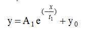
The thermal and electronic properties of LED compounds were further investigated by using quasi harmonic Debye model [12]. The aspect of chromaticity shift of LEDs towards shorter wavelengths is also demonstrated by lighting engineers and illustrated by Stark effect [6]. It was explored by Narendran that the light output of the LEDs is related by the following relation as given in equation (1).
where 'y', 'α' and 't' represent the relative light output, decay constant, and time in hours, respectively. It was later investigated that 'α' relates with the current drawn by the device. Hence controlling of drive current but maintaining the light output of the device is still a challenge for researchers[11].
Further in 2012 researchers while studying reliability of LEDs explained as many as thirteen different reasons for LED failure. However it was understood that thermal management is the most crucial aspect of LED failure [2].
In this paper, various photometric parameters, CCT is chosen and the subsequent variation with respect to the ambient temperature is recorded. The LEDs are subjected to minimum temperature change between on time and off time[2]. It must be understood that apart from junction temperature the test point temperature commonly referred as T-point temperature also plays a pivotal role in LED luminaire design. This is because T-point temperature defines the size of the heat sink required to dissipate the quantum of heat from the device. In the forthcoming discussion, it shall unfold that how often the ambient temperature and T-point temperature can be correlated with CCT for the LEDs in use. It must be understood that phenomena of colour shift shall not be considered when LEDs are classified as general light source.
The research work carried out so far is an attempt to investigate the underlying aspects of LED lifetime prediction against the changes in ambient temperature. It was earlier explored that the light output of the LEDs degrades drastically with any incremental changes in the solder point temperature. Extended further it was observed and tabled that the light output of the LEDs are influenced with changes in ambient temperature. The work carried out in this paper reflects those parametric alterations in light output of the LEDs with respect to the Correlated Colour Temperature (CCT) and thus the quality of light emitted gets influenced. As evident from the plots the CCT can be related with ambient temperature. This study is further extended to the fact that in case of dimming using PWM the impact it has on CCT alongside the ambient temperature is also investigated and formulated.
The experiment consists of a LED packages inside a test chamber fitted in a LED life test rack. The life test rack has been designed to be subjected to accelerate test. The change in on time and off time temperature is chosen as a parameter to establish stress on the device under test. The corresponding light output is measured and the change in temperature is recorded using a thermocouple. The life test rack is equipped with the function of integrating sphere and an environment chamber capable of temperature changes. The sample size used for the experiment is fifteen each 5 mm high flux LED. The lamps are aged for 100 hours before the start of experiment. The temperature inside the sphere is controlled by a temperature controller and observed by a pair of thermocouple fixed inside the sphere [2]. The lamps are labelled as L1, L2, L3, L4, L5, L6, L7, L8, L9, L10, L11, L12, L13, L14, and L15. The driver circuit for L1 is designed using PWM dimming technology by IC VIPer 12A. It is a monolithic device with integrated PWM controller [1]. The rest are made commercially available incorporated with boost converter circuit.
The driver circuit used for L1 is equipped PWM dimming. The aspect of dimming in LEDs is basically of two types: (a) analog (b) PWM dimming. In the case of analog dimming, 50% brightness is achieved by providing 50% of the maximum current to the LED using TPS 61500 IC. This method has got serious drawbacks relating to colour shift. In PWM dimming full current is applied to the LED with reduced duty cycle. For 50% brightness full current is applied at 50% duty cycle. However, the frequency of PWM signal must be above 100 Hz to reduce the perception of flicker to the human eye. The basic drawback of PWM equipped driver is since the LEDs are subjected to constant current drive the requirement of overvoltage protection becomes more essential. Several overvoltage protection is in practice. In the proposed zener diode circuit is connected in parallel to the diodes.
In the design suggested as shown in Figure 1 VIPer 12A of ST Microelectronics is used as driver control IC. It has integrated PWM controllers.
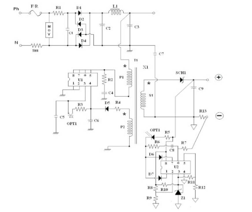
Figure 1. PWM Dimming Circuit using VIPer 12A IC
The design operates from 90VAC to 240VAC ±5 % input. At the starting of the circuit a fusible resistance is connected to protect the circuit from overcurrent. A Metal Oxide Varistor (MOV) protects from the surge voltage which is occurred for inductive switching in supply line. Thermistor TH1 protects the circuit from starting inrush current. The AC input is rectified and filtered by the bridge rectifier made with D1 D2 D3 & D4 to generate the high voltage DC bus that is applied to the primary winding of the transformer, X1. C1, L1, C2, and C3 provide EMI filtering for the circuit. A3 winding transformer is used in this circuit, out of three windings two P1 & P2 are used for power transformation and S1 is used for giving feedback to U1 through OPT1.
A snubber circuit consists of R2 and C4. It reduces the leakage spike and voltage ringing on the drain pin of U1 (i.e. VIPer12A), thereby provides additional EMI filtering. The current is controlled by monitoring the voltage drop across the sense resistor, R13. The non inverting input of the operational amplifier inside U2 (i.e. LM358) is set to 200 mV through the resistors divider, R8 & R9 and R11 & R12 and one voltage reference of 2.5 V from Z1 (i.e. TL431). This operational amplifier will then regulate the inverting input to 200 mV by adjusting its output by changing the current going through the optocoupler, OPT1. The gain of the transistor inside the optocoupler then controls the feedback loop of U1. The LED drive current is given as,
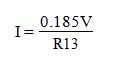
where R13= 0.5Ω, Iout = 370 mA
C5, C8, and R6 are utilized to ensure the stability of the circuit. R3 is used for capacitor C5 charging and C5 is taking the feedback voltage storage. C9 reduces the ripple current. As a safety measure, a resistor divider consisting of R8 and R9 is added to clamp the output voltage fed back into U2 so that it does not exceed the maximum voltage rating of U2 for a no load condition at the output. Here U2 has two internal comparators one is for voltage reference and another for current reference. The load (LED) is connected through SCH1 which is used for ultrafast switching [5], [7], [8].
The experiment is carried out with the set of samples available. The CCT for the lamps is measured with Minolta Chroma Meter. The measurement is carried out in two steps.
The LEDs are 5 mm high flux pure white InGaN having composition of InGaN and CCT in the range of 6000 degree Kelvin. The set of plots define the characteristics of the LEDs against dimming and ambient temperature. The ambient temperature and T-point temperature is related by an empirical relation as,
where 'y' and 'x' represents T-point temperature and ambient temperature (Ta) in degree Celsius, respectively. The terms 'A1', 't1 ' and 'yo' are constants having values as 1.5532, 19.23, and 35.75, respectively [10].
From the plot as shown in Figure 2, it is evident that CCT for all the lamps decreases with increase in ambient temperature and T-point temperature. The curve fitting is plotted using MATLAB 2013.
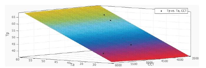
Figure 2. Plot CCT versus T-point (Tp) versus Ambient Temperature (Ta) without Dimming
The curve fitting equation hence evaluated for the best fit is as follows,
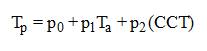
The co-efficients are obtained with 95% bounds.
p0 =8.85(-18.05, 35.75)
p1 =0.9402(0.6767, 1.204)
p2 =0.0006482(-0.00287, 0.004167)
The corresponding R-square for the above fit has been evaluated to be 99.2%.
The second plot as shown in Figure 3 has been obtained with 50% dimming.
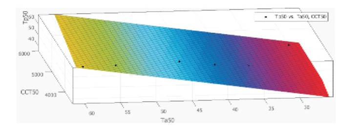
Figure 3. Plot of CCT versus T-point Temperature (Tp) versus Ambient Temperature (To) with 50% Dimming
It is observed that L1 is the only LED that could sustain a CCT of 3543 degree K even at 60°C ambient temperature. All the other LEDs had drastic fall in the CCT when the ambient temperature increased from 45 °C to 60 °C. The relation holds true even at 50% dimming as defined in equation (4). The LED under observation were not fully equipped to sustain a high ambient temperature keeping intact the CCT. That implies with rise in ambient temperature the LED would be subjected to colour shift.
It is understood that the LED drivers play a major contribution towards maintaining the CCT of the lamp intact. It is thereby implicative that the quality of light output of the LEDs degrades drastically with the rise in ambient temperature. It has been established that any change in ambient temperature influences not only solder point or T-point temperature, but also correlated colour temperature. Henceforth, the quality of light for a LED in the long run is very much influenced by change in ambient conditions. In areas wherever specific lighting requirements are mandatory the quality of light is an important aspect. It becomes for a lighting engineer thereby to check the light quality emitted by LEDs in such areas of strategic importance. Moreover, the work also explores the aspect of energy saving as it takes into account of dimming of LED and the subsequent impact it has on CCT alongside the change in ambient temperature. Thus in a hot and humid environment the performance of the LED with respect to their life and light requires substantial development.
The basic concept of the study is primarily attributed to the work carried out by various researchers particularly by Marc, Narendran, Biermann, and Klein as published in 2005. It was suggested that the chromaticity shifts for phosphor coated white LEDs using PWM techniques is within the allowable limit which was justified using McAdam ellipse.
The current research work as presented in this paper takes into consideration of the aspects and dimming and hence proposes a reliable circuit so that impact of dimming will not sustain the chromaticity shift within allowable range. Further it also correlates the ambient temperature and dimming along with the correlated colour temperature. Thus taking into account an empirical relation upholding the influence of ambient temperature and the subsequent impact it has on the quality of light from LEDs. In fact the aspect of life of LEDs are perhaps less discussed as it has been assumed to be 'infinite' as compared to the contemporary light sources. Many a places where it has been used very less attention has been made to the life of these sources. The aspect of light output with increase in ambient temperature has been addressed and a relation hence formulated as published in 2016 by Mukherjee and Soni. It was established that the LED light output drops off exponentially with increase in ambient temperature. Thus making it vulnerable to use in hot and humid climatic conditions.