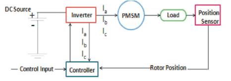
Figure 1. PMSM Drive System
In the present circumstances, industries are highly increasing and demanding process in all sectors. Permanent Magnet Synchronous Motor gives better results in quality, increased production, and reduced costs. Permanent Magnet Synchronous Motor (PMSM) drive plays a vital role in each and every industry. There is a necessity to upgrade the models of the electric motors and drives for a better simulation. This paper introduces the design and evolution of a simulation platform of PM Synchronous Motor drive. This paper provides advanced modeling and Matlab simulation tools for PM Synchronous Motor drive to designers and the developers of electric motor drive control systems allowing them to model the independent components using the appropriate software. This paper shows the methodology to interface PMSM Motor on a single simulation platform. In this work, the electric machine model is developed using MATLAB software. Whereas the power electronic converter and PMSM drive control models are designed using mathematical equations in MATLAB/SIMULINK.
Today most of the drives used in the industries are electrical. Depending on the application, some have fixed speed and some of them variable speed. In a permanent magnet motor operating on a fixed frequency AC supply, the constant rotor flux produced by the permanent magnets generates a constant value of excitation Emf, Ef. The actual value of excitation Emf depends on the magnet material, its physical dimensions, the rotor design, and the air gap length. The machine designer must ensure that the magnets are not demagnetized by the application of normal or overload currents.
The elimination of field coils, DC supply and slip rings minimize the PMS motor loss and the complexity. These motors are then well known as brushless motors and have increasing applications in robots and machine tools. The PMSM can be fed either rectangular current or sinusoidal current. The rectangular current fed motors which have concentrated windings on the stator inducing a square or trapezoidal voltage are normally used in low power drives. The sinusoidal current fed motors, which have distributed windings on the stator, provide smoother torque and normally used in high power drives.
Presently, the design, growth and easier implementation of Permanent Magnet (PM) materials have to carry an extended use of Permanent Magnet Synchronous Motors Drives (PMSMs) in high performance different speed motors for many automated applications. In this paper, a brief description of the Mathematical model and simulation of the PM Synchronous Motor (PMSM) drive is presented along with the corresponding block diagram realization in the MATLAB/SIMULINK background presented in [1- 4], [13].
PMSM is high-performance different speed motors for many automated applications. Basic advantages of using a PM Synchronous Motor (PMSM) drive, includes high reliability, less maintenance, and high efficiency. The PMSM motors are generally chosen in the highperformance drives, where the specific performances justify the costs, higher than other motors with the same torque, but realized with a different technology. PMSM are used in highly reliable direct-drive applications mainly due to their advantages. Compared to standard DC motors, they have no brushes or mechanical commentators, which eliminate the issues due to mechanical wear of the moving parts. In addition, the better heat dissipation characteristic and ability to operate at high speed make them a better option. Figure 1 shows PM Synchronous Motor Drive system. It consists of the stationary member of the machine called stator. Stator laminations for axial air gap machines are frequently formed by winding sustained strips of soft steel. Varied parts of the laminations are the teeth slots whichever carry the armature windings. Yoke finishes the magnetic path. Armature windings are a commonly duplex layer (two coil side per slot) and lap wound. Individual coils are connected successively to form phasor groups. Phasor groups are associated successively in series/parallel integrations to form a twophase (or) single windings. AC windings are in general short pitched to diminish harmonic voltage generated in the windings. Figure 2 shows the construction diagram of PMSM Drive [3, 4, 9, 10, 11, 13].
Figure 1. PMSM Drive System
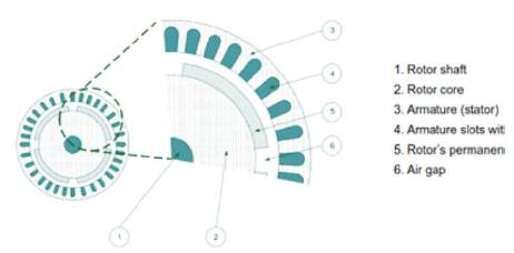
Figure 2. Shape of PM Synchronous Motor Drive
From Figure 3, it can be determined that an equivalent two-phase circuit model of a three-phase PM synchronous machine (interior and surface mount) is derived in order to clarify the concept of the transformation (Park) and the relation between threephase quantities and their equivalent two-phase quantities [5], [6].
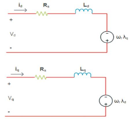
Figure 3. Equivalent Circuit of PMSM Drive
To derive the two-phase (d-q) mathematical model of PMSM, the following assumptions are made.
Comparing a primitive version of a PMSM with wound-rotor synchronous motor, the stator of a PMSM has windings similar to those of the general wound-rotor permanent magnet with respect to the rotor should be considered in the dynamic d-q model of a PMSM. From the equivalent circuit, mathematical modeling equations can be determined as follows,
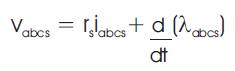
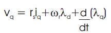
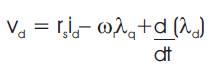

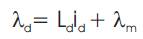
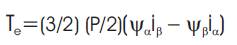
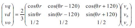
Parks Transformation is given by,
MATLAB/SIMULINK is a numeral computing background and fourth-generation machine language. Developed by MathWorks, this software allows matrix control, the scheme of functions and data, execution of algorithms, the creating user combines, and interfacing with programs written in other languages. Although MATLAB/SIMULINK is predetermined mainly for numerical count, an individual toolbox uses the Mu PAD significant engine, allows access to significant computing capabilities. An additional and extra add-on combination of packages, Model-Based Design for embedded systems and dynamic and Simulink, adds graphical multi-field simulation [7, 9, 10, 11, 12].
The emphasis between modeling and simulation can enhance the quality of the system design early, thereby decreasing the number of errors found later in the design process [7, 8, 12, 14].
Simulation is a procedure in which you verify and validate a model by differentiating simulation results with the following,
The simulation is performed workflow after the model is completely developed and a simulation completes without errors. The steps in a common simulation progress includes,
Figure 4 shows the construction of simulation model. For the first simulation, use model parameters from the validated model. After differentiating the simulation results with sustained output data, change model parameters to more accurately represent the modeled system. Using sustained input data run a simulation. Figure 5 shows the procedure to run and evaluate simulation model [7, 8, 12, 14].
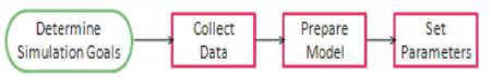
Figure 4. Simulation Model Block Diagram
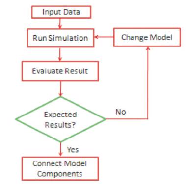
Figure 5. Run and Evaluate Simulation Model Block Diagram
The Model-Based scheme is a process that enables fast and cost-effective design and development of dynamic systems, contains control systems, signal processing, and communications systems. The model is an executable framing that you continually process through the development process. After model development, the simulation shows in case the simulation model works correctly [7, 8, 12, 14].
As software and hardware implementation specifications are involved with the model, such as stabled-point and timing mode, one can develop code for embedded deployment and create test work tables for system validation, saving time, and stay out manually coding errors [7, 8, 12, 14].
The Model-Based scheme allows for better efficiency by,
Simulink prepared to think of the design and development environment as a laboratory for modeling and analyzing systems that would not be possible or practical otherwise [7, 8, 12, 14].
In case, one is intented in the performance of an automotive clutch system, the flutter of an airplane wing, or the response of the industrial supply on spending, Simulink also gives examples that model a wide range of real-world development [7, 8, 12, 14].
MATLAB/SIMULINK includes a graphical editor for constructing models as simulink block diagrams, the editor allow to draw the models. Simulink also includes a substantial library of the sink, source, basic linear and nonlinear elements, and connector blocks. If the given blocks do not meet the needs, one can also design their own blocks. The interactive environment simplifies the modeling process, eliminating the need to formulate differential and difference equations in a language or program. Models are pecking order, so you can build models using both top-down and bottom-up access. They can have point view of the system at a high level, and then drill down to see increasing levels of model detail. This approach gives insight into how a model is classified and how parts interact [7, 8, 12, 14].
After the model is formulated, it can simulate its dynamic presence using a support of mathematical implementation methods, either indicatively in Simulink or by using commands in the MATLAB/SIMULINK Command Window. Commands are principally helpful for processing a set of simulations. Using scopes and other display blocks, the results can be viewed during simulation runs [7, 8, 12, 14]
The model analyzes the tools involved for linearization and trimming tools from MATLAB/SIMULINK, plus the several tools in MATLAB/SIMULINK and its application toolboxes. Because both MATLAB/SIMULINK are integrated, then simulate, understand, and revise the models in either background [7, 8, 12, 14].
The simulation diagrams for the above mathematical modeling equations of PMSM are mentioned in Figures 6 - 8 [1-4], [11, 13].
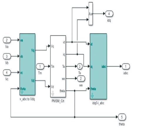
Figure 6. Simulation Diagram for abc to dq Conversion
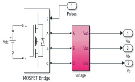
Figure 7. Simulation Diagram for PWM Inverter
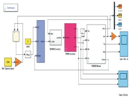
Figure 8. Overall Simulation Diagram for PMSM Drive
Figure 8 shows the overall simulation diagram of PMSM with load designed based on modeling equations of PMSM. In the same figure, Parks Transformation is applied for a d-q model of PMSM and also PWM Inverter is designed and fed to the PMS.
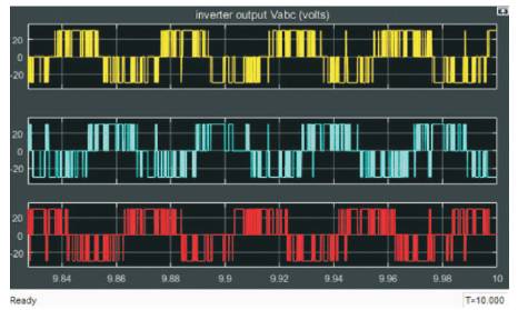
Figure 9. Simulation Results for Va , Vb , and Vc
Figure 10 shows the simulation results for voltages at the inverter Va , Vb , and Vc in volts, which is fed to the PMSM Model to allow the currents Ia , Ib , and Ic into the machine.
Figures 10 - 12 show the simulation results for currents Ia , Ib and Ic in Amps at a phase difference of 120 degrees each.
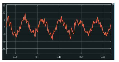
Figure 10. Simulation Results for Ia
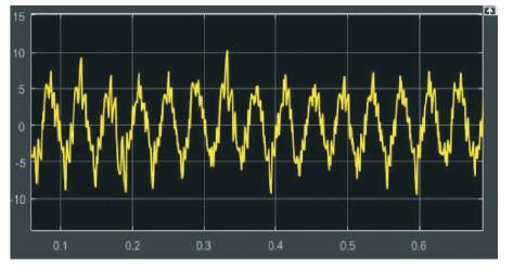
Figure 11. Simulation Results for Ib
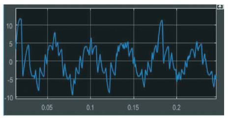
Figure 12. Simulation Results for I c
Figure 13 shows the simulation results of Speed, Torque, daxis, and q-axis currents. In PMSM, speed is maintained constant because it is a constant speed machine, which can run at a synchronous speed only. In Figure 13, Id =0 because the method for PMSM applied is vector control method due to which the torque is also maintained in steady state.
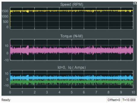
Figure 13. Simulation Results for Speed, Torque, and I dq
This paper demonstrates the development of a dynamic model of a PMSM. The main contribution includes the development of each and every block of a PMSM from the first principle. Also, Parks Transformation is studied and their subsequent Simulink models are developed. The complete vector control scheme is implemented and is tested with Parks Transformation. The plots obtained demonstrate that the PMSM Model and its subsequent MATLAB/SIMULINK implementation gives satisfactory results. The model developed follows the standard mathematical relationships. All the control equations governing the dynamic model are kept intact. This model gives expected results in simulation showing the performance of PMSM.
I am very happy to be a part of the electrical world as a researcher. And I wish to thank all authors who supported me to write this paper. The paper, participating in its early stage and giving the idea to extend it up to a review paper. I would also like to thank the colleagues and friends for their fruitful cooperation, contribution, and discussions. My special thanks to my husband for complete support to do this paper.