[1]
In this paper, a mathematical model of PMSM is analysed using the dominant simulation modelling capabilities of MATLAB/SIMULINK. One of the most efficient control strategies of PMSM is Vector control. There are several independent functional module, such as coordinate transformation module, PMSM body module, inverter module, controller modules, and some other modules which play an important role in controlling of PMSM. The combination of these modules results in simulation model of the PMSM control system. The model has many advantages in simulation. The detailed structure of the simulation model in MATLAB/SIMULINK is presented. Finally, a simulation example is proposed to verify the feasibility.
In applications, where high performance is demanded, some properties of the Permanent Magnet Synchronous Motor, such as high torque, high power, high efficiency, and low noise have made it more popular compared to other alternating motors.
The various control strategies for the control of the inverter fed Permanent Magnet Synchronous Motor have provided good steady-state, but poor dynamic response [3]. The cause of poor dynamic response is that the air gap flux linkages deviate from their set values. The deviation is not only in magnitude, but also in phase. The variations in the flux linkages have to be controlled by the magnitude and frequency of the stator and rotor phase currents and their instantaneous phases. So far, the control strategies have utilized the stator phase current magnitude and frequency not their phases. So for the control of PMSM we are using FOC scheme [2], [4].
The PMSM equations are developed in rotating reference frames, assumptions in developing the mathematical model are as follows,
Rotating reference frame (d-q) machine equations are as follows,
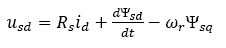
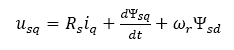
Stator voltage equations,
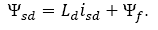
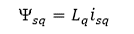
Stator magnetic flux linkage equations,
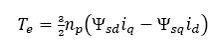
Electromagnetic torque equation,
Motor movement equation,
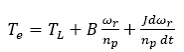
where, usd, usq, isd, isq, Ld, Lq are respectively the voltage, current and inductance on d, q axis. Rs, ωr,Ψf are the stator resistance, electric angular speed, and permanent flux, respectively. Te, TL, B, np, and J represent electromagnetic torque, load torque, viscous friction coefficient, number of pole pairs, and total moment inertia of rotor and load, respectively [2, 6].
Vector control made the AC drives equivalent to DC drives in the independent control of flux and torque and superior to them in their dynamic performance [1]. The fundamental basic diagram is shown in Figure 1.
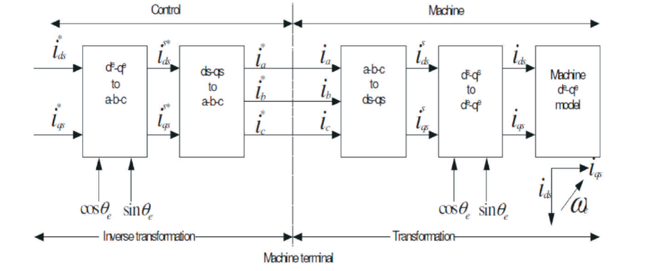
Figure 1. Block Diagram of Vector Control
The simulation model of vector controlled permanent magnet synchronous motor is shown in Figure 2. The sampling time used in model is 2 e-0006 μs. Parameters of motor are listed in Table 1. The main controllers in this model are speed controller and vector controller [5]. All the parameters and ratings used in the simulation are shown in Table 1.
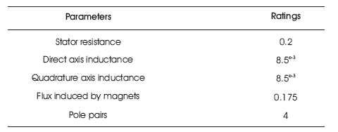
Table 1. Parameters and rating
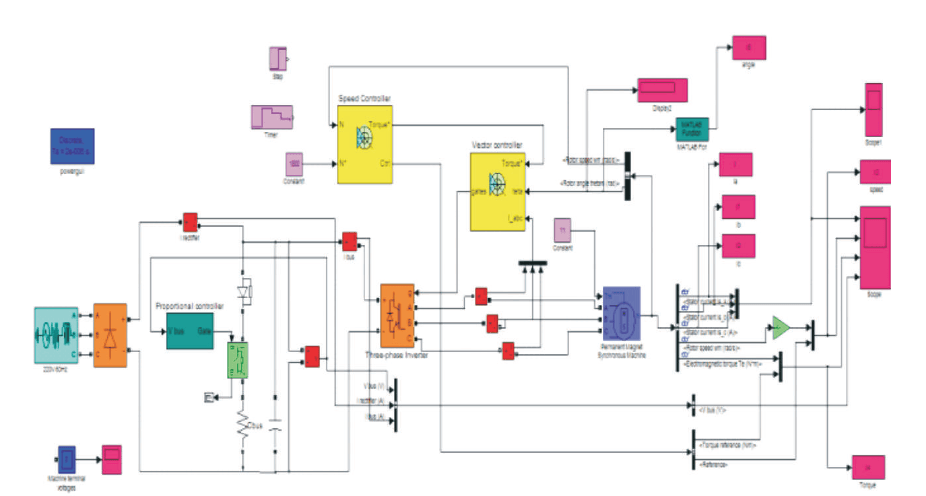
Figure 2. Simulation Diagram of Vector Control of PMSM
With the simulation of the motor, the diversity of simulation waveforms can be analyzed and it provides a valuable means for the analysis and design of the PMSM control system. These waveforms offer an effective means for the analysis and design of the PMSM control system. Following are the waveforms of stator current, electromagnetic torque, and speed which are based on different values of speed and torque like step changes, and both periodic changes, variation in speed and torque.
Figures 3 - 5 show the output waveforms of armature current, rotor speed, and electromagnetic torque, respectively of PMSM for Ns of 900 r.p.m. and constant load torque.
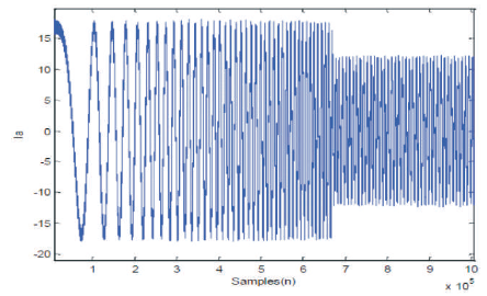
Figure 3. Output Response of Armature Current I (Amp) for a N = 900, T = 11
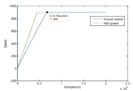
Figure 4. Output Response of Rotor Speed (w) for m N = 900, T = 11
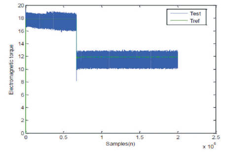
Figure 5. Output Response of Electromagnetic Torque (T ) m for N = 900, T = 11
Figures 6 - 8 show the output waveforms of armature current, rotor speed and electromagnetic torque respectively of PMSM for Ns of 2000 r.p.m. and constant load torque.
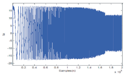
Figure 6. Output Response of Armature Current I (Amp) a for N = 2000, T = 11
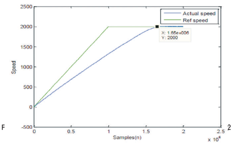
Figure 7. Output Response of Rotor Speed (w) m for N = 2000, T = 11
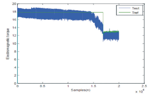
Figure 8. Output Response of Electromagnetic Torque (T ) m for N = 2000, T = 11
Figures 9 - 11 show the output waveforms of armature current, rotor speed, and electromagnetic torque, respectively of PMSM for step change in Ns from 400 to 1200 r.p.m. and constant load torque.
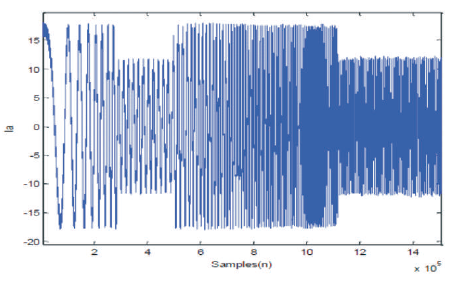
Figure 9. Output Response of Current Armature I (Amp) a for N = 400 - 1200, T = 11
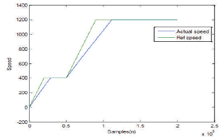
Figure 10. Output Response of Rotor Speed (w) m for N = 400 - 1200, T = 11
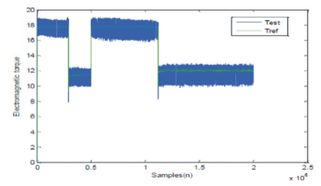
Figure 11. Output Response of Electromagnetic Torque (T ) m for N = 400 - 1200, T = 11
Figures 12 - 14 show the output waveforms of armature current rotor speed and electromagnetic torque, respectively of PMSM for step change in Ns from 1200 to 1800 r.p.m. and constant load torque.
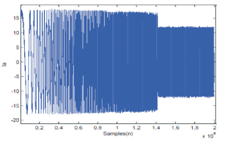
Figure 12. Output Response of Current Armature I (Amp) for a N = 1200 - 1800, T = 11
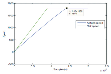
Figure 13. Output Response of Rotor Speed (w) m for N = 1200 - 1800, T = 11
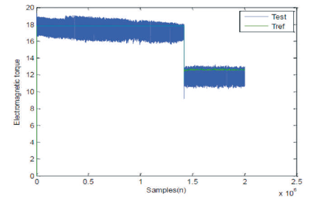
Figure 14. Output Response of Electromagnetic Torque (T ) m for N = 1200 - 1800, T = 11
Figures 15 - 17 show the output waveforms of PMSM for Ns =1200,1500,1700,1800, and Tm periodic change in value of the output waveform of armature current, rotor speed and electromagnetic torque, and constant load torque.
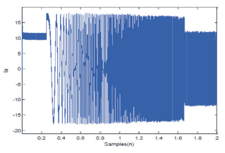
Figure 15. Output Response of Armature current I (Amp) a for N = 1200, 1500, 1700, 1800, T = 11
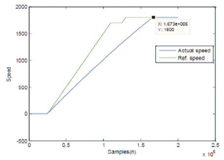
Figure 16. Output Response of Rotor Speed (w) for m N = 1200, 1500, 1700, 1800, T = 11
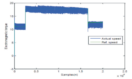
Figure 17. Output Response of Electromagnetic Torque (T ) m for N = 1200, 1500, 1700, 1800, T = 11
Figures 18 - 20 show the output waveforms of PMSM for Ns = 400, 600, 1200, 1800 and Tm= 11 periodic change in value of the output waveform of armature current, rotor speed and electromagnetic torque, and constant load torque.
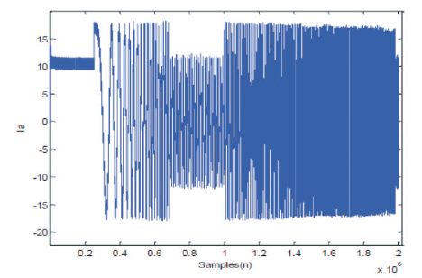
Figure 18. Output Response of Armature Current I (Amp) for N = 400, 600, 1200, 1800, T = 11
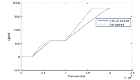
Figure 19. Output Response of Rotor Speed (w) m for N = 400, 600, 1200, 1800, T = 11
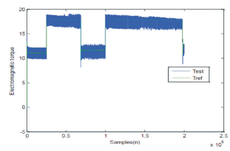
Figure 20. Output Response of Electromagnetic Torque (T )
In this paper, an overview of vector controlled Permanent Magnet Synchronous Motor has been presented with their respective advantages and disadvantages. Applications where high performance is demanded, some properties of the permanent magnet synchronous motor, such as high torque, high power, high efficiency, and low noise have made it more popular compared to other alternating current motors. With the simulation of the motor, the authors have analyzed a diversity of simulation waveforms and it provides a valuable means for the analysis of the PMSM control system. In the future works, this algorithm will be extensively tested in the speed controlled drive system of PMSM. The simulation model of PMSM control system is established using Simulink toolbox of MATLAB.