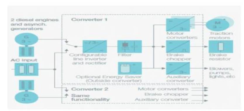
Figure 1. Proposed Hybrid Drive by Bombardier (MITRAC) [12]
Retention of Passenger and Freight Trains working on Electric Traction at Stations in the event of Grid Failures / Locomotive Failures cause inconvenience to passengers and delay in delivery of freight, thereby causing losses in revenue. As Traction is a high Power Application, delivery of Power of the order of 1600 kW per Traction Motor would also cause stresses in the Switching Devices in a 3-φ Converter System. In order to overcome stress on Switches, a new Drive System using 5-φ Inverter driven Permanent Magnet Synchronous Motor as Traction Motors that can run on both Electric and Diesel-Electric Traction is proposed by the authors in this research paper.
Failures can occur anytime. There can be grid failure or failure in traction sub-station or failure in the locomotive itself like rectifier fault. These types of failures would lead a train being retained at a station, which may lack even basic facilities causing a lot of inconvenience to the passengers. Another aspect to be considered is traversing of a train from electrified to non-electrified section and vice versa. Instead of waiting for a new locomotive to take over hauling, the same locomotive can take the train along in both the sections, thus saving the time required for locomotive change. Given this scenario, a locomotive with a traction drive system capable of traversing both electrified and non-electrified sections with the same ease would be an advantage and can save lot of time and earn more revenue with better turn-around time. With railways all over the world researching for a dual supply locomotive[2] and with bombardier undertaking a pioneering research to build hybrid locomotives called MITRAC, the design of which is shown in Figure 1 [12], the authors propose a hybrid traction drive system with Head- On-Generation capability using 5-φ Permanent Magnet Synchronous Motors (PMSM) [4] as traction motors in this research paper.
Figure 1. Proposed Hybrid Drive by Bombardier (MITRAC) [12]
The first objective is to design a traction drive system that can work on both 1-φ, 25 kV, 50 Hz, AC supplied through over head equipment and also on 3-φ, 4 kV, 50 Hz, AC supplied from the diesel engine driven traction alternator along with capability of head-on-generation for the electrical loads of the trailing passenger coaches and auxiliary loads of the locomotive. The second objective of this research paper is to reduce the stresses on the switching devices and reduce the failures due to overloading of switches as observed in the 3-φ converter systems. In order to minimise the stresses on the switches in the traction inverters for delivering high power and also work on both electrified and non-electrified sections, a 5- φ inverter [1], [7] ,[8],[9]driven Permanent Magnet Synchronous Motor drive is proposed and simulated as the technology of the future for hybrid locomotives. The speed control is implemented by means of space vector PWM commanded by an embedded MATLAB program. Six PMSMs of the rating of 5-φ, 1000 kw, 4 kV, 2-poles are used in this simulation of hybrid traction drive system.
The description of drive system of a dual power supply hybrid mixed locomotive with 5-φ PMSMs as traction motors is given in four Parts and the block diagram is shown in Figure 2. The supply system and rectifier units for operation on 25 kV, 1-φ AC is described in first sub- section. In the second sub-section, the diesel-engine driven alternator system and 3-φ rectifier units are described. In the third sub-section, a description of the DC link, traction inverter system and the traction motor connections are given. In the fourth sub-section, a description of the power supply system for the auxiliary loads of the locomotive as well as HOG [3] for trailing passenger coaches in case of the working of the locomotive as passenger variant is given. The simulink connection diagram of the traction drive system of hybrid mixed locomotive is shown in Figure 3. A brief description of the construction of the new improved drive circuit for hybrid mixed locomotive is given below.
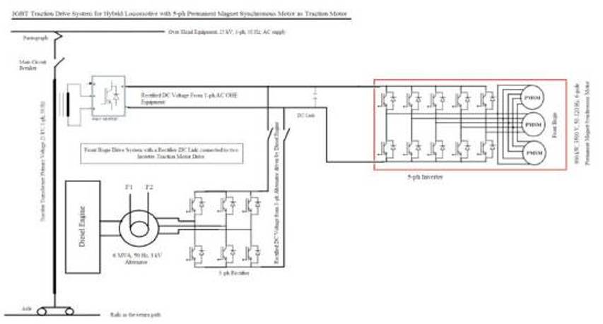
Figure 2. Block Diagram of Traction Drive System for Hybrid Locomotive with 5-φ PMSM as Traction Motors for a Bogie
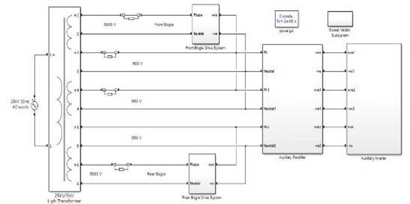
Figure 3. Simulink Connection Diagram of Traction Drive System for Hybrid Locomotive with 5-φ PMSM as Traction Motors
A multi-winding 1-φ transformer is used in this circuit. The ratings of the transformer are 25 kV, 1-φ, 50 Hz AC on the primary side and 4 kV, 1-φ, 50 Hz on the secondary side. Two tapings of 4 kV each are taken in the secondary side to be connected to traction rectifiers. Three tapings of 1 kV each are connected to the auxiliary rectifiers to supply power to the auxiliary loads of the locomotive and trailing passenger coaches in electric traction mode.
Two 4-pulse bridge rectifiers with IGBTs as switches are connected in parallel to form one unit of traction rectifier. The input to the rectifier is 4000 V, 50 Hz AC supply fed from an AC source through the main transformer. There are two rectifier units in the proposed circuit for Traction drive in each of the two bogies. Each Rectifier Unit has its own sinusoidal PWM generator. The 4-pulse bridges would be operational in electric mode of traction. The output of the rectifier is fed to the DC Link. The connection diagram of 1- φ rectifier-DC link sub-system is shown in Figure 4.
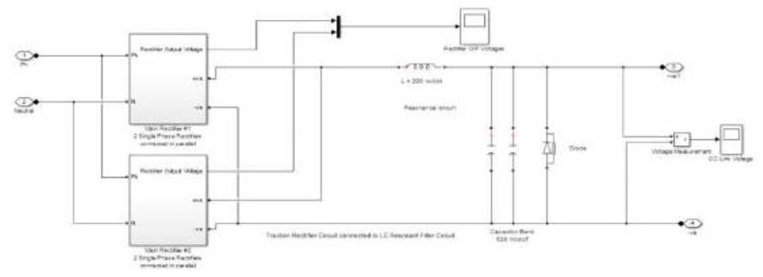
Figure 4. 4-Pulses Bridge Rectifier - DC Link Circuit
The traction alternator used in this simulation for hybrid locomotive is a 6 MVA, 3500 V, 50 Hz synchronous machine. The machine is adapted to work on constant power mode of operation. The machine is rated to work at 1000 rpm and has 6-poles. This synchronous machine is driven by a diesel engine adapted from the ACIA excitation system in electric drives library of the MATLAB simulink software[11]. Two alternators are used in this simulation study (one each per bogie to drive three traction motors).
Two 6-pulse IGBT bridge rectifiers are used in a converter system. The rectifier output voltage is a pulsating DC of magnitude of about 3500 V. The rectifier is controlled by means of a sinusoidal PWM generator. A resistance of 5 MΩ is connected to the bridge rectifier in both the bogies for introducing braking in diesel mode of traction. Two circuit breakers are provided at the output side of the rectifier to make and the connection from the DC link to alternate between 25 kV 1-φ supply and alternator supply during the running of the locomotive. The connection diagrams of 3-φ rectifier-DC link sub-system diesel engine - traction alternator are shown in Figure 5 and Figure 6 respectively.
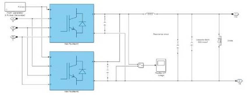
Figure 5. 6-Pulses Bridge Rectifier - DC Link Circuit
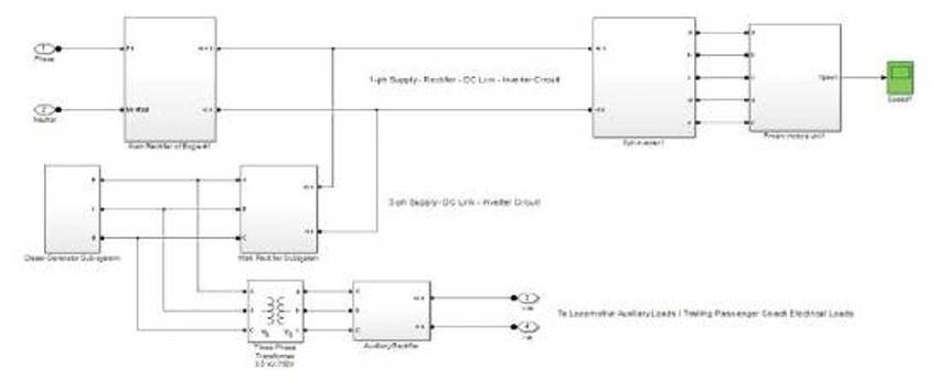
Figure 6. Rectifiers - DC Link - Traction Inverter Circuit
The traction rectifier output of both the types of supply circuits is connected to the DC link. The DC link consists of a capacitor bank of 815 μF and 11.41 mF connected in parallel to filter out the harmonics in the DC voltage. A diode is connected in the DC link to ensure unidirectional current. The output of the DC link is connected to the traction inverter.
The traction inverter is a 10-Pulse bridge inverter circuit with IGBTs as switching devices and is capable of generating sine waves displaced by a phase difference of 72˚. The pulses are delivered by means of a Space Vector PWM generator such that the frequency of inverter operation can be varied according to the speed required at the wheel through Variable Voltage Variable Frequency (VVVF) method [1], [5], [6], [7] The output of the traction inverter is fed to a set of three traction motors connected in parallel. The simulink diagram of rectifiers - DC link - traction inverter circuit is shown in Figure 7.
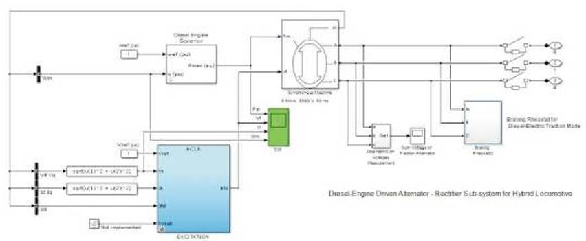
Figure 7. Diesel-Engine driven Alternator - 3- φ Braking Rheostat Connection Diagram
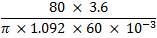
Six PMSM [4] ,[9] are used as traction motors in this drive circuit. The traction motors are rated at 1000 kW, 4 kV, 2- poles, 50-125 Hz as operating frequency. The V/f constant for the rated voltage and frequency is (4 kV)/(50 Hz) = 80.
Power has to be supplied to the auxiliary loads of the locomotive and the trailing passenger coaches (in case of hauling passenger trains) by means of head on generation in the locomotive itself in either modes of traction. For the purpose of supplying power to the Auxiliary Loads in electric mode of traction, three tapings of 700 V each are taken off the Secondary Winding of the Traction Transformer and are connected to Diode Bridge Rectifiers. With a Filter capacitor of 815 mF, a Diode Bridge Rectifier is connected to IGBT Inverter pulsed by a sinusoidal PWM Generator. In order to supply power to the Auxiliary Loads of the Locomotive on non-Electrified section, two 3-φ Step-down transformers of the rating of 3 kV/750 V are connected to the traction alternator. The combined Load handling capacity of the transformers is designed to about 700 kVA (with capability of HOG). Two Diode Bridge Rectifiers are connected to the output terminals of the Transformers. The outputs of the rectifiers are connected to the Auxiliary Inverter through Auxiliary DC Link mentioned above. Again, the Hotel Loads of the Locomotive are segregated in this simulation into two parts, namely the Loads operable in Electric Mode of Traction and Loads operable in Diesel-Electric Mode of Traction. The Hotel Loads of the Locomotive operable during the Electric Mode of Traction like the Transformer Oil Pump Motor, Scavenge Blowers for Transformer are operated only when the Input supply is 1-φ, 25 kV, AC.
The Hotel Loads like radiator fans, fuel oil pump motors, and lubricant oil pump motors are operated only when the supply is 3-φ, 3.5 kV, AC from the traction alternator. Other Hotel Loads like the traction motor blowers, scavenge blowers for traction motors, brake grid blower motors, cab lighting equipment, converter blowers, and converter cooling oil pumps along with loads of the trailing passenger coaches are operated in both modes of traction. The operation of locomotive Hotel Loads is switched between the electric mode and diesel-electric mode by means of circuit breakers. The simulink connection diagram of the power circuit of the auxiliary loads of the locomotive are broken into parts and are shown in Figures 8-11.
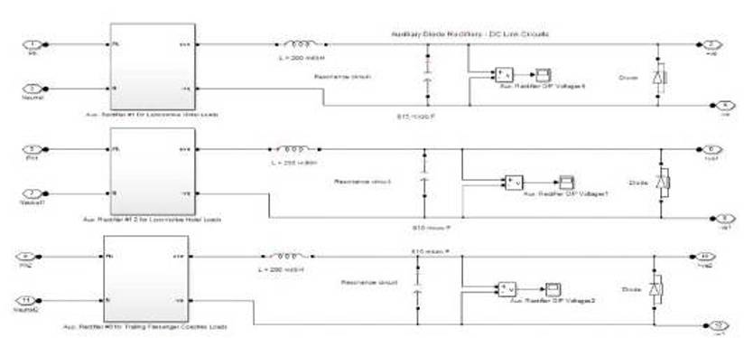
Figure 8. Auxiliary Rectifiers - DC Link Circuit
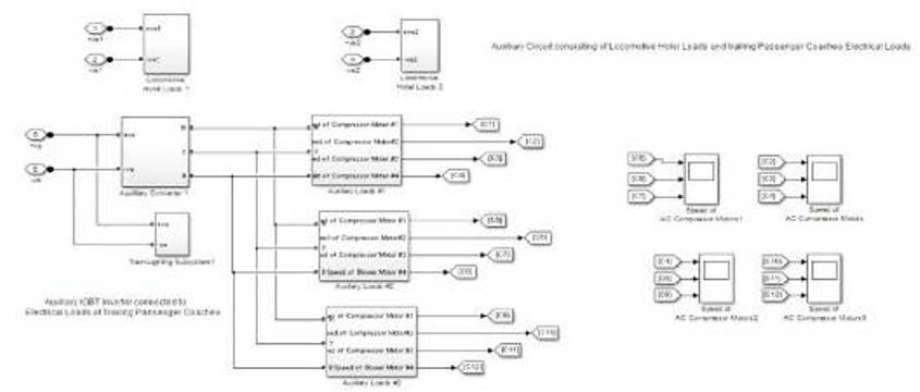
Figure 9. Connection Diagram of various Auxiliary Loads
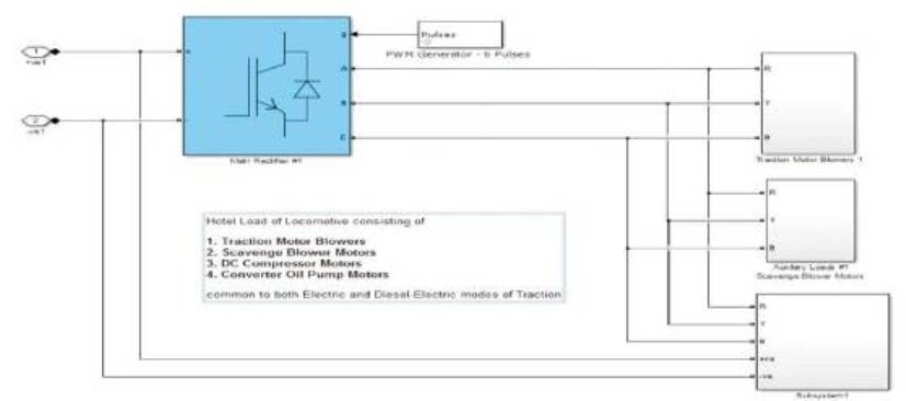
Figure 10. Connection Diagram of Hotel Loads common to both types of Traction
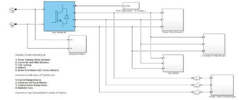
Figure 11. Connection Diagram of Hotel Loads of the Locomotive
The simulation of the circuit for dual supply locomotives with hybrid drive system was carried out with a long freerunning period - a characteristic of high speed express trains. In addition, the operating speed of the traction motors on electric traction mode has been set to 160 kmph (the latest Speed limit set for Semi-high Speed Trains in India). The simulation of the circuit shown in Figure 3 was carried out for a period of 45 seconds of the MATLAB simulink time.
The simulation is initialised with supply from the 1-φ, 25 kV, AC source at 50 Hz frequency. The output of the 3-φ traction alternator is diverted to the 5 MΩ rheostat, such that diesel-electric traction mode is kept switched off. The 4-pulse bridge rectifiers are pulsed from the PWM Generator at twice the line frequency. Pulsating DC voltage was observed at the output terminals of the 4- pulse bridge rectifiers in both bogies. The output voltage waveform of the 4-pulse bridge rectifier is shown in Figure 12. It can be observed that the voltage builds up steadily and is constant at 4500 V till the initiation of rheostatic braking at time t=10 seconds. At time t=10 seconds, the circuit breakers on the input side of the 4-pulse bridges (Pulsations are ceased) are opened and the braking chopper is pulsed so that the braking rheostat is brought into the circuit to absorb the circulating current in the DC link due to the discharging of the LC filter components. The speed required at the wheel during this period from time t=0 seconds to t=10 seconds is set to 120 kmph, which corresponds to a speed of 2098 rpm for the traction motors. The speed command is delivered from an embedded MATLAB Program, which calculates the frequency of operation and voltage of the traction inverter. The switching times of the IGBTs in the traction inverters is determined by the Space Vector PWM Generator sub-system according to the required frequency of operation of the inverter[1]. At the end of the braking period at time t=14 seconds, the circuit breakers on the input side of the 4-pulse bridge rectifiers are still kept open and the circuit breakers on the input side of the 6-pulse bridge rectifiers connected to the traction alternator are closed and the rectifiers are pulsed from Sinusoidal PWM Generators at double the line Frequency to filter out harmonics. The voltage steadily built up from 'zero' to 3000 V resulting in the traction motors accelerating to a speed of 1400 rpm corresponding to set speed of 80 kmph in a few milliseconds. The 3-φ traction alternator output voltage waveform can be observed in Figure 13.
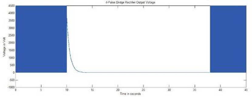
Figure 12. 4-Pulse Bridge Rectifier Output Voltage Waveform
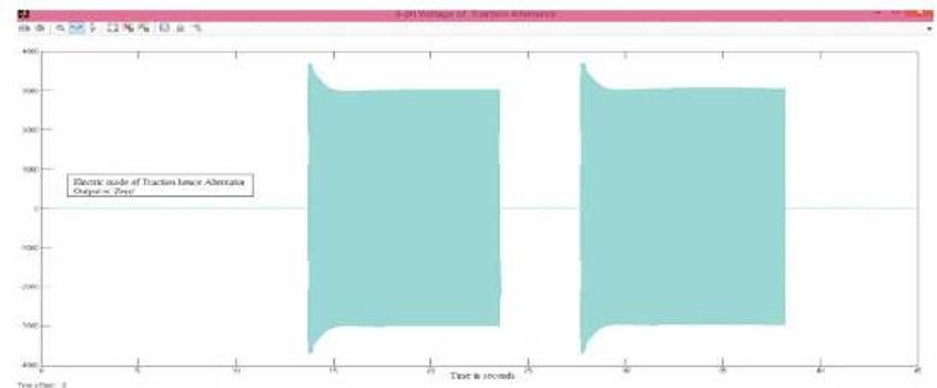
Figure 13. 3-φ Traction Alternator Output Voltage Waveform
The voltage observed in the common DC link is shown in Figure 14. It can be seen in the DC link voltage waveform graph that, the voltage raises and falls gradually during initiation and braking, respectively. The free-running period on diesel-electric mode of traction is maintained till time t=24 seconds (period of 10 seconds after Notching-Up and Acceleration) after which braking is initiated by ceasing the pulsations to the 6-pulse bridge rectifiers and diverting the generated voltage to the 3-φ braking rheostats connected to the traction alternator output terminals by closing of 3-φ circuit breaker. The voltage in the traction inverter steadily fell to 'zero' as also The speed of the traction motors. the traction inverter output voltage waveform is shown in Figure 15. Again, at time t=28 seconds, the alternator is reconnected to the traction drive circuit and the generated voltage of 3.5 kv is imposed on the 6-pulse bridge rectifiers. The inverter voltage is also slowly built up to 3000 V. The speed of the traction motors slowly rose to 1400 rpm corresponding to set speed of 80 kmph at the wheel. The mode of traction is changed at the instant time t=38 seconds from dieselelectric mode to electric mode by closing the circuit breakers on the output terminals of the traction transformer and connecting the 4-pulse bridge rectifiers. At the same time, the circuit breakers connecting the traction alternator output terminals to the load/braking rheostats are 'closed', thereby diverting the 3-φ alternator voltage to the load rheostat. The voltage in the 4-pulse bridge rectifier and in turn in traction inverter slowly builds up to 3800 V as shown in the respective graphs. In order to demonstrate the operability of the traction drive system at higher speeds, the speed required at the wheel is set to 160 kmph (concept of Semi-high Speed Trains proposed by Indian Railways).
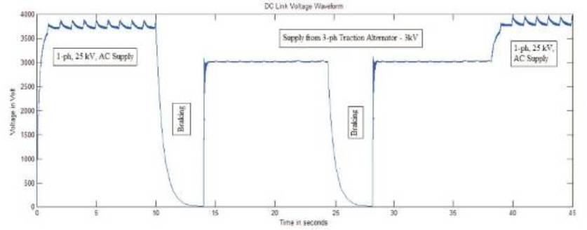
Figure 14. DC Link Voltage Waveform
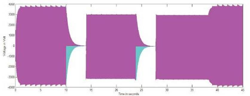
Figure 15. 5-φ Traction Inverter Output Voltage Waveform
The speed of the traction motors observed during this period was 2798 rpm. The speed-time curve of the traction motors in rpm and the corresponding speed in kmph expected at the wheel of the locomotive is shown in Figures 16 and 17 respectively with necessary tagging for notching-up, acceleration, free-running periods, and braking in both electric and diesel-electric modes of traction. The versatility of changing from diesel-electric to electric mode of traction and vice-versa with/without braking was demonstrated in this simulation study. The transitions were observed to be smooth with very less transients while changing from one mode of traction to the other. The same drive system can be used with a modified gear ratio for freight locomotives. The voltage levels are maintained to near required values according to the V/f constant computed.
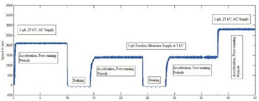
Figure 16. Speed-Time Curve of Traction Motors in rpm
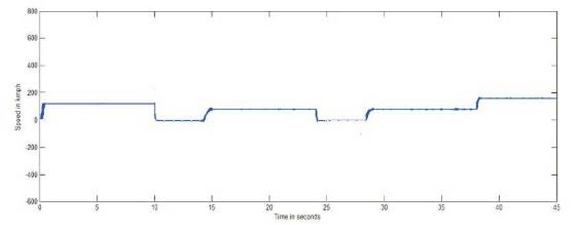
Figure 17. Speed-Time Curve in kmph expected at the Wheel
The auxiliary loads have been segregated according to their usage in electric and diesel-electric modes of traction. The auxiliary loads of the locomotive that have to work in either modes of traction are supplied power from two auxiliary windings of the traction transformer during the electric mode of traction. The third auxiliary taping from the secondary of the traction transformer is exclusively used for delivering power to the airconditioning systems and train lighting systems of the trailing passenger coaches. The auxiliary loads of the locomotive comprising of fuel oil pumps, lubricant oil pumps and cooling water circulation pumps are operated only during diesel-electric mode of traction and are switched off in electric mode of traction. a diode bridge rectifier rectifies the voltage of 700 V obtained from the secondary auxiliary winding of the traction transformer. The harmonics in this pulsating DC are filtered out in the DC link, which consist of a inductor of 200 mH and a capacitor of 815 mF. The near straight line DC thus obtained is fed to IGBT inverter pulsed at industrial frequency of 50 Hz. The auxiliary DC link and auxiliary inverter output voltage waveforms are shown in Figures 18 and 19 respectively. Twelve squirrel cage motors of the rating of 22 kW are connected in parallel to the 3-φ Inverter connected to the third auxiliary taping of the traction transformer to simulate the air-conditioning compressor motors of the air-conditioned coaches. Thirty six 1- φ RLC loads are connected to balanced 3-φ supply to represent the train lighting system of the passenger coaches. During the diesel-electric mode of traction, this load of the passenger coaches are supplied exclusively from the second traction alternator through a 3-φ transformer of the rating of 3 kV/415 kV. Hence, there is no interruption in power supply to the electrical loads of the trailing passenger coaches in either modes of traction. The speed-time curve of the AC compressors are shown in Figure 20.
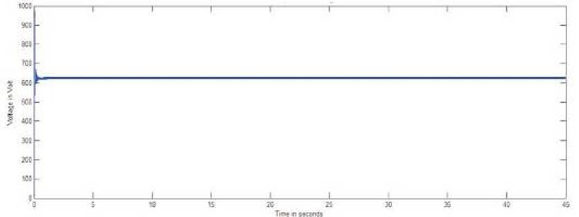
Figure 18. Auxiliary DC Link Voltage Waveform
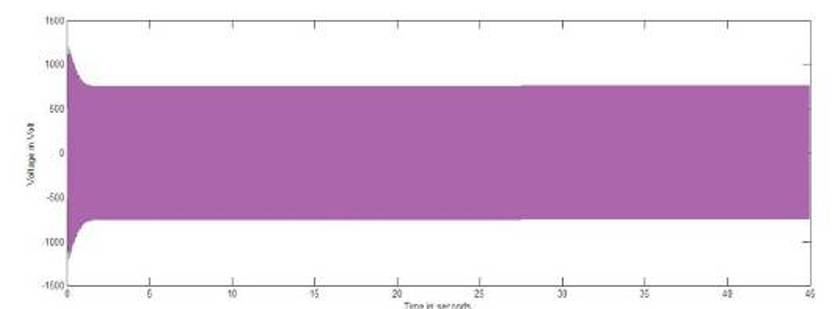
Figure 19. 3-φ Auxiliary Inverter Output Voltage Waveform
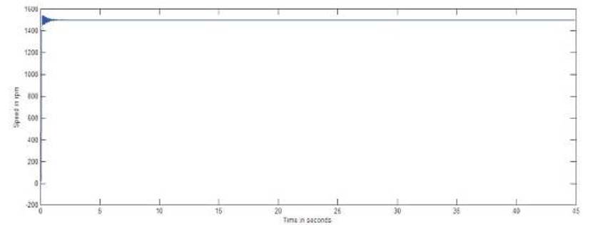
Figure 20. Speed-Time Curve of Air-conditioning Compressor Motors
The Hotel Loads of the locomotive like the blower motors for the traction motors and converters, scavenge blowers to blow away the dust, brake grid blower motors are common to both types of traction and have to be kept running in either modes of traction. On electric mode of traction, these loads are supplied with power from the secondary winding of the traction transformer and during the diesel- electric mode of traction, these loads draw power from the traction alternator through the 3-φ auxiliary transformer. The traction converter blowers are squirrel cage induction motors of the rating of 22 kW/ 6- poles working on 3-φ, 415 V with a synchronous speed of 1000 rpm. The speed-time curves of the scavenge blowers and converter blowers are shown in Figures 21 and 22 respectively. Six squirrel cage induction motors of rating of 22.5 kw and 2-poles are used as traction motor blowers in this simulation. Hence, the speed developed by these blowers is 2990 rpm. The speed-time curve of traction motor blowers is shown in Figure 23. The transformer oil circulating pump is used to circulate the cooling oil in the traction transformer. Hence, it has to work only in electric mode of traction. This pump is supplied power from the auxiliary winding drawn from the secondary of the traction transformer through auxiliary rectifier - inverter circuit. It can be clearly seen in Figure 24 that, the transformer oil pump motor does not work in diesel-electric mode of traction.
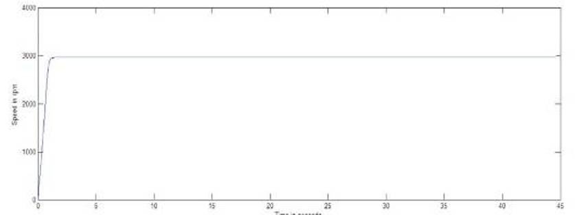
Figure 21. Speed-Time curve of Scavenge Blower Motors
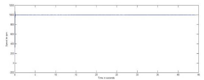
Figure 22. Speed-Time Curve of Traction Converter Blower Motors
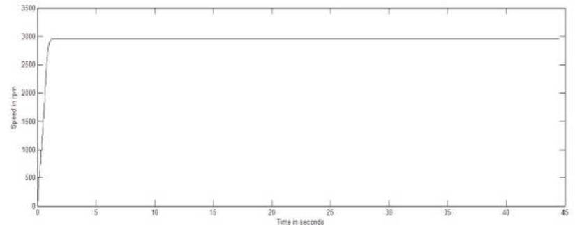
Figure 23. Speed-Time Curve of Traction Motor Blower Motors
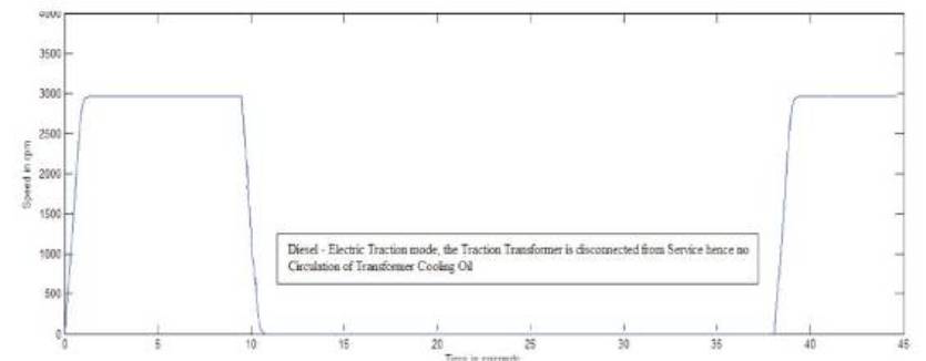
Figure 24. Speed-Time Curve of Traction Transformer Oil Pump Motor
The loads like the fuel oil pumps, lubricating oil pumps, cooling water circulation pump and radiator fans are worked only during the diesel-electric mode of traction by drawing power from the 3-φ step-down transformer connected to the output terminals of the traction alternator. In this simulation study, the above mentioned loads are disconnected by means of a circuit breaker at their respective input terminals in the auxiliary circuit during the electric mode of traction. This is depicted in the speed-time curves of the fuel oil pumps and radiator fans shown in Figures 25 and 26 respectively. Six squirrel cage induction motors of the rating of 7.5 kW/8-poles are used as radiator fans (fans used to cool the diesel-engines), resulting in a speed of about 750 rpm. DC motors (both shunt and series types) are used in locomotives.
In case of electric locomotive, DC shunt motors are used as compressors so as to produce compressed air for the air brake system of the locomotive and the coaches/wagons, for raising the pantograph and maintaining it at certain height so that it makes contact with the catenary wire. In diesel-electric locomotives, DC series motors are used for blowing compressed air in to the braking rheostat grids. Hence, both the types of DC motors are used in this simulation - to produce compressed air. The speed-time curve of the DC shunt motor and series motor are shown in Figures 27 and 28 respectively. Batteries are used in electric locomotive to initially start the motor for lifting the pantograph. In diesel-electric locomotives, they are used to start the DC motor required to give the initial excitation for the alternator. Therefore, batteries have to be kept charging in either modes of traction and the percentage battery charging is shown in Figure 29.
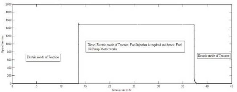
Figure 25. Speed-Time Curve of Fuel Oil Pump, Lubricant Oil Pump and Cooling Water Pump Motors for Diesel-Engine
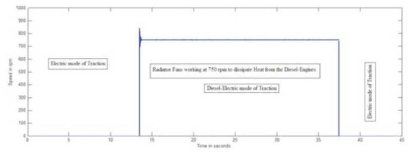
Figure 26. Speed-Time Curve of Radiator Fans
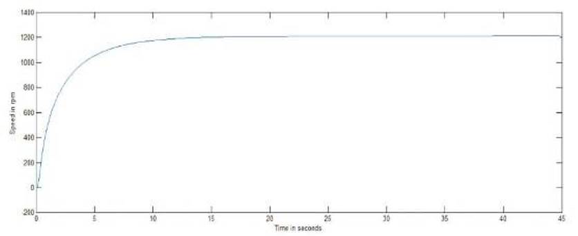
Figure 27. Speed-Time Curve of DC Compressor Motor (DC Shunt Motor)
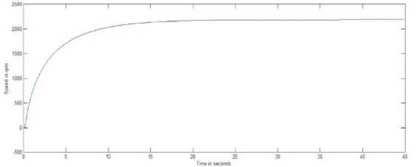
Figure 28. Speed-Time Curve of Brake Grid Blower Motors (DC Series Motor)
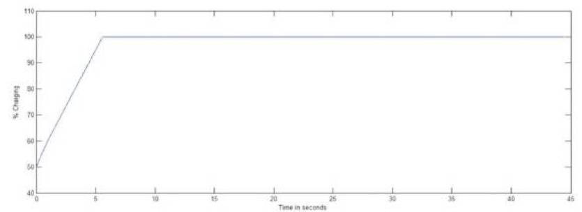
Figure 29. Percentage Battery Charging
It is assumed that the locomotive starts on a plane surface without gradient and curvature, hence the initial tractive effort required would be only tractive effort for acceleration. At the same time, it has also been considered that the locomotive may have to start on a curve, go up a gradient immediately. Hence, the maximum tractive effort[10] to be developed under these conditions is also calculated and the required ratings of traction motors are suggested. The nonpremium superfast trains are taken as reference for the purpose of calculations. The details of the various types of passenger coaches that make a train formation have been taken from Table 1. Let us assume that the locomotive has to accelerate a trailing load to 120 kmph in 500 seconds.
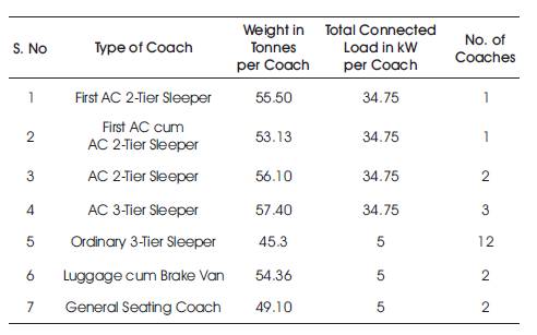
Table 1. Details of Ordinary Passenger Coaches [3]
Acceleration, α in kmphps will be given as, α = 120/500 = 0.24 kmphps
Weight of the Trailing Load = Wt = Wt = [(1×55.5)+ (1×53.13) + (2×56.10) + (3×57.40) + (12×45.3)+ (2 ×54.36) + (2×49.10)] = 1143.55 Tonnes
Total Weight = W = (W1 + Wt ) = 1263.55 tonnes
Weight of the Locomotive = W1 = 120 tonnes
Tractive Effort required for Acceleration = Fa = 277.8 ×1389.9×0.24=93 kN
Tractive Effort required to overcome Train Resistance at 120 kmph is calculated as,
Fcr = 9.81 × 1143.55 [(1.424)+(0.0054 ×120)+(0.00025 ×1202 )]
Newton = 9.81 ×1143.55 ×5.672=63.62 kN
Tractive Effort required for Locomotive to overcome Train Resistance at 120 kmph is calculated as (Fr),
= 9.81×(0.65WI +13 n+0.01 WI v+0.052 v2) = 9.81×1048.8=10.3 kN
Total Tractive Effort required to overcome Train Resistance for a Passenger Train ( Ftr),
Ftr = Fr + Fcr = 73.92 kN
Fc = 9.81 W (700/R) Newtons = 9.81 ×1263.55 (700/600) Newton = 14.4 kN
Tractive Effort to overcome Gravitational Pull ( Fg ),
Fg =9.81 W.G Newtons = 9.81×1263.55×0.1=1.24
kN
Total Tractive Effort = Ft = Fa + Fr +
Fc + Fg = 93+74+14.4 +1.24 =182.64 kN
Max. Power Output required at the Axles = Pmax
= [0.277 ×182.64×120] kW = 6070 kW
The Total maximum Tractive Effort required = Ft ≥ 182.64 kN, if all the Tractive Efforts are taken into consideration, but at the Speed of 120 kmph, the Tractive Effort required would be the Tractive Effort to overcome Train Resistance after the acceleration.
There are six Traction Motors in this Variant of Locomotive. Hence, the Maximum Power Output required per Traction Motor = 6070 ÷ 6 = 1011 kW
Assuming a Motor Efficiency of 95%, the Power Input to be given to a Traction Motor = 1011 ÷ 0.95= 1065 kW
Taking into considerations, the variations in working conditions, the 5-φ Permanent Magnet Synchronous Motors used as Traction Motors are rated at 1000 kW each for Locomotive.
Voltage per phase = 3500 V
Current per phase = 90 A
Power Factor = 0.86 (Assumed)
Efficiency of the Machine = 95% (Assumed)
Frequency = 50 Hz, No. of Poles = 4, Diameter of the
Wheel = 1092 mm
Efficiency of the Gear = 0.9
Gear Ratio for Passenger Locomotive = Gr = 3.6
Power input to the PMSM at Starting
= 5 x Vph x Iph x Cosφ Watts
= 5 x 3500 x 90 x 0.86 Watts
= 1354.5 kW (per Motor)
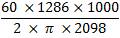
Power Output per Motor = 0.95 x 1354.5 = 1286 kW
Rated Speed of the Traction Motors = Ns = (120 ×f)/p rpm = (120 ×75)/4 = 2250 rpm
If the Speed of the Locomotive is 120 kmph, then the Speed of the Traction Motors will be Ntm .
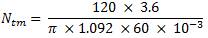 rpm=2098 rpm
Torque developed per Motor =  Nm
Nm
 Nm=
5853 Nm
Nm=
5853 Nm
Total Torque developed by 6 Traction Motors,
Td = 35120 Nm
Tractive Effort Developed (at Speed of 120 kmph)
 =
=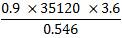 =208 kN
Voltage per phase = 3000 V
Current per phase = 100 A
Power Factor = 0.86 (Assumed)
Power input to the PMSM = 5 x Vph x Iph x
Cosφ Watts
= 5 x 3000 x 100 x 0.86 Watts
= 1290 kW (per Motor)
Power Output per Motor = 0.95 x 1290 = 1225 kW
If the Speed of the Locomotive is 80 kmph, then the Speed of the Traction Motors will be Ntm
 rpm= 1399 rpm
Torque developed per Machine = Nm =
Nm =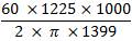 =8362Nm
Total Torque developed by 6 Traction Motors,
Td = 50170 Nm
Tractive Effort Developed,
= =
= 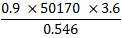 =297kN
If the Speed of the Locomotive is 120 kmph, then the Speed of the Traction Motors will be Ntm = 2098 rpm.
Torque developed per Machine = Nm
Nm
 Nm = 5575 Nm
Total Torque developed by 6 Traction Motors,
Td = 33454 Nm
Tractive Effort Developed,
 =
= = 198.5 KN
Let the total Distance covered by the Passenger Train be 3000 kms.
Ea= 0.01072 x V m2x We = 0.01072 x 1202 x 1389.9 = 214556 Wh
Eg = Fg x D1 Watt hours = 1.24 kN x 10 = 12400 Wh
where D1 = Distance for which Power is 'On'.
Er = Fr x D2 = 0.277 x W x r x
D1 Wh
= 0.277 x 73.92 x 2900 = 59379936 Wh
where D1 = Distance for which Power is 'On'.
Total Energy Output of driving Axles =
Ea + Eg + Er = 214556 + 12400 + 59379936 = 59606892 Wh
Specific Energy Output =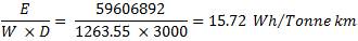
Where, D = Total Distance travelled by the Train.
Specific Energy Consumption
=
Power required for 7 AC and 16 non-AC Coaches =
[(34.75 x 7) + (16 x 5)] = 323.25 kW
Assuming a diversity factor of 0.7, the Maximum Demand at any given time for Passenger Coaches = Ppmax = Diversity Factor ×Total Connected Load = 0.7×323.25 kW Pmax = 227 kW.
The total Auxiliary Loads of the Locomotive connected when the Locomotive is running on 25 kV, AC Supply is = PImax1 = 178.2 kW, if the Traction Motors are self-Ventilated. If the Traction Motors are not self-Ventilated, then the total connected Auxiliary Loads are = 310.2 kW. The total Auxiliary Loads of the Locomotive connected when the Locomotive is running on 3.5 kV, AC Alternator Supply is = PImax2 = 189 kW, if the Traction Motors are self-Ventilated. If the Traction Motors are not self-Ventilated, then the total connected Auxiliary Loads are = 321 kW.
The total Load = Ppmax + PImax1 = 227+178.2 = 405.2 kW
Output Voltage of Auxiliary Winding of Transformer = 650 V
Output Current of Auxiliary Inverter = 75 A
Output Power at each Auxiliary Inverter terminals fed from Auxiliary Windings of Transformer = √3×V ×I ×Cosφ = √ 3 ×650 ×75 ×0.86 = 73 kW
Total Output Power from Six Auxiliary Inverters = 6 ×73 = 438 kW.
The total Load = Ppmax + PImax2 = 227+189 = 416 kW
Output Voltage observed at the Auxiliary Inverter Terminals =650V
Output Current of Auxiliary Converter = 75 A
Output Power at each Auxiliary Inverter terminals fed from 3-φ Step-Down Transformer = √ 3×V ×I ×Cosφ = √ 3 ×650 ×75 ×0.86 = 73 kW
Total Output Power from six Auxiliary Inverters = 6 ×73 = 438 kW
It can be concluded from the power calculations, that all the six auxiliary inverters have to be kept switched 'ON' in both electric and diesel-electric modes of traction to enable Head on Generation of power for auxiliary loads of the locomotive and electrical loads of trailing passenger coaches.
The conclusions drawn from the simulation studies of traction drive system for dual supply locomotives are that,
Hence, it is concluded that this Hybrid Traction Drive System can be implemented as the Technology of future for Locomotives in India.