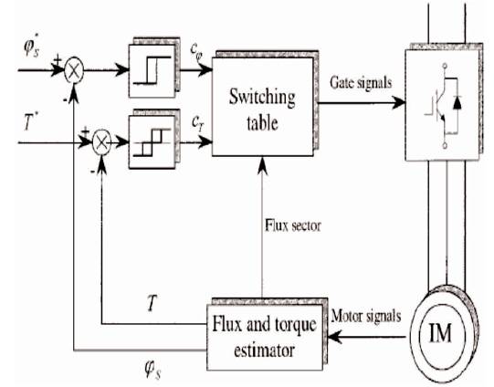
Figure 1. Basic Block Diagram of DTC
This paper presents the operation of Space Vector Modulation (SVM) based DTC scheme for a Voltage Source Inverter fed Induction Motor Drive. Firstly, the performance of existing model is studied with Fuzzy Logic Controller. In order to incorporate better dynamic response, the discussed model is further simulated using Adaptive Fuzzy Controller. Simulations results obtained with these controllers are presented and compared. It may be inferred that Adaptive Fuzzy based model exhibit better operational features with regard to torque and flux response. The performance of this control method has been demonstrated by simulations done using MATLAB/SIMULINK tool.
Motion control applications require frequent torque control to adjust the speed of the electrical drive. The induction machine is most widely used machines in industrial applications due to its high reliability, relatively, low cost, and robust construction. Decoupled torque and flux control is to be established in an electrical drive to achieve better performance. Such type of control is offered in a dynamic approach by the Direct Torque Control, which is a well-known control technique for Induction Motor. This method provides good dynamic response compared with other control methods like Field Oriented Control (FOC) (P. Vas, 1998). The DTC has been proposed for an Induction Motor Control in 1985 by (Takahashi & Noguchi, 1986), and with similar idea the name of Direct Self Control method was developed in 1988 by(Novotny & Lipo, 1996). From then, the DTC has gained much attention due to its merits like simple control structure, insensitive to the machine parameters variations, good dynamic response, unneeded current regulators, etc. However, DTC method(Bertoluzzo, M., Buja, G., & Menis, R. 1999) has fewer disadvantages and they can be summarized as follows,
Further various PWM methods have been utilized in conjunction with DTC to overcome the demerits and among such is Space Vector PWM technique (Rashid & Luo, 2006).
On the other hand, intelligent controlling methods like Fuzzy Logic Controller have been developed by the research community for its potential in the design process. The FLC has gained great attention in every area of electromechanical devices control due to absence of mathematical models for systems unlike conventional controllers in (B.K. Bose, 1986). This fuzzy logic controller method provides good dynamic performance and robustness.
In this paper, to reduce the torque ripples of the DTC based Induction Motor Drive, a novel technique has been proposed called Adaptive Fuzzy Logic based Space Vector Modulation method (AFL-SVM). The Adaptive Fuzzy Logic Controller(Wang, L.X., 1994) in this proposed method acts with speed and unit delay speed errors as input and produces an output to minimize flux and torque errors. Further FLC drives PI controller for controlling action. The simulation results have been derived from MATLAB/SIMULINK and finally comparative studies have been presented for the proposed control method.
The main objective of the current work is to enhance the induction motor performance using SVM-DTC technique and to enable the drive system to operate accurately during dynamic load variations.
The basic block diagram used to implement the DTC (Bertoluzzo, Buja, & Menis, 1999) and(Tao & Liang, 2011) scheme in an induction motor is shown in Figure 1. Three phase AC supply is given to the uncontrolled diode bridge rectifier which produces a DC voltage. A high value DC link capacitor is used to control the ripple content in the DC voltage. The filtered DC quantity is the power supply to the inverter switches. The Voltage Source Inverter (VSI) comprises of IGBT switches(B.K. Bose, 1986), which are controlled by the direct torque control algorithm. The output of the VSI is connected to the stator terminals of the induction motor.
Figure 1. Basic Block Diagram of DTC
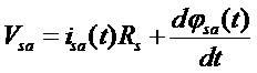
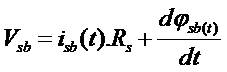
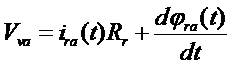
The flux and torque are calculated from the machine terminal voltages and currents. The computation block can also calculate the sector number, where the flux vector lies. The phase voltages and currents in stationary reference frame are shown below.

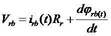
The direct and quadrature component of stator flux is given by,
The scalar value of the stator flux can be estimated by,
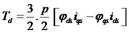
The flux vector zone can be obtained by using the stator flux of direct and quadrature components. By using the flux components, current components and IM number of poles, the electromagnetic torque can be calculated by,
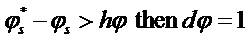
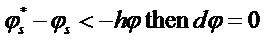
The values of flux and torque are calculated from stator variables by using flux and torque estimator block. The reference stator flux and torque magnitude are compared with their respective estimated values and then the errors are processed by the hysteresis controllers (F. Blaschke, 1972). The flux hysteresis controller has two levels of digital output according to following expressions.


Here bandwidth =2hφ
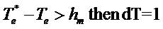
where 2hφ is the total hysteresis bandwidth of the flux controller. Similarly, the torque control loop has three levels of digital output represented by the following expressions,
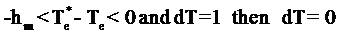
If
If
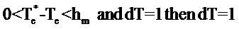
If
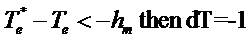
If
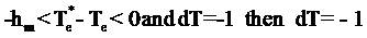
If
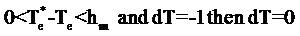
If
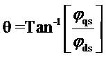
In DTC method, stator flux vector, the rotate trajectory is divided into six regions and the well-defined stator flux region directly affects the control performance. The stator flux d-q(R.J. Lee, P. Pillay, & R.G. Harley, 1984) components that are calculated can be used for the defining of the stator flux region as given below,
These observed error values of the flux and the torque are compared to the reference flux and torque values and the resultant errors are applied to the hysteresis controllers as inputs. Two different hysteresis controllers generate some other control parameters on the DTC ( Liang, 2011)method. According to the hysteresis comparators outputs, the observed flux angle and using a switching table, optimum voltage vectors are selected and applied to the invertermethod. According to the hysteresis comparators outputs, the observed flux angle and using a switching table, optimum voltage vectors are selected and applied to the inverter(Ben-Brahim & Kurosawa, 1993).
Here the objective of Space Vector Pulse Width Modulation technique is to get the demanded output voltage instantaneously from the combination of the different switching states corresponding to the basic space vectors(Narasimham, 2010). These switching states when represented by peak voltage, the vector magnitude forms a hexagonal structure (Gupta & Gupta, 2012) as shown in Figure 2. The number sectors are based on the type of inverters used in the control design(M.L. Swarupa, G.T.R. Das, P.V. Gopal, 2009).
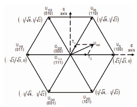
Figure 2. Six Voltage Switching Vectors
Fuzzy Logic Control (FLC) is an algorithm based on a linguistic control strategy which tries to use the human's knowledge about how to control a system without using any mathematical model of a system. The block model for fuzzy logic controller system is shown in Figure 3.
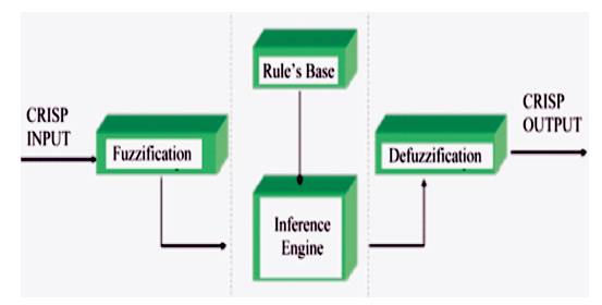
Figure 3. Fuzzy Logic Controller
The design of any Fuzzy Logic Controller needs the good choice of Membership Functions. The membership functions are chosen in such a way that they should cover the whole universe of discourse. For better controlling action, the membership functions near the zero regions should be narrow. Wider membership functions are used away from the zero regions, which provide faster response to the system. Hence, the membership functions should be changed accordingly.
After selecting the appropriate membership functions, the fuzzy rule base should be created. It is having a number of Fuzzy If-Then rules that shows the behaviour of the system. These rules very much resemble the human thought process, thereby providing artificial intelligence knowledge to the system. In this paper, 7x7 rule base are used, which has 49 rules. The membership functions for two inputs and one output are same, which is shown in Figure 4 and FLC surface is shown in Figure 5.
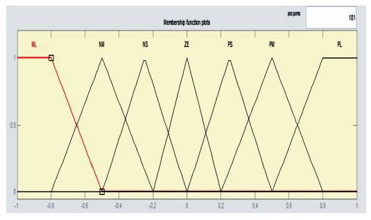
Figure 4. Membership Functions
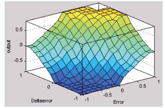
Figure 5. Surface of the FLC
In Adaptive Fuzzy logic controller [14], FLC are used to drive the conventional controllers like PI, PD and PID controllers. Here FLC drives the PI controller, such that it gives better controlling action compared to FLC controller.
In this section, the Matlab/Simulink is used to simulate the SVM DTC system to examine the performance of an induction motor. Figure 6 represents the simulink model of the proposed controller used for the considered system.
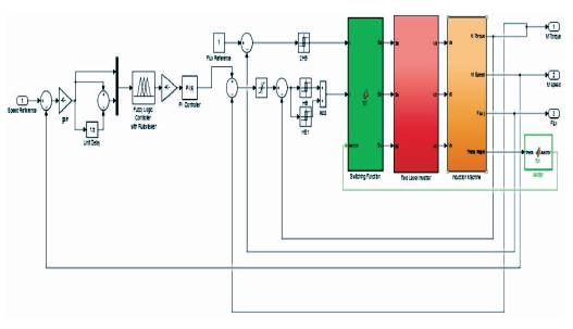
Figure 6. Simulink Block Diagram for the Proposed Method (SVM DTC using Adaptive Fuzzy Controller)
Test cases for understanding the results are based on the three torque values. Load Torque at initial state of the drive, i.e. 0 Nm, Load Torque at time 0.4 sec, i.e. 15 Nm, and finally Passive Load Torque at time 0.8 sec, i.e. -20 Nm.
The simulation studies reveal the following results. The torque response for speed at 150 rad/sec which is fixed and the reference flux is 1.0 Wb, the initial value of load torque is 0 Nm as shown in Figures 7 and 8. When at 0.4 sec, the load torque was set at 15 Nm; The simulation time is 1.0 second as shown in Figures 9, 10, 11 and 12. It represents the torque response at fixed speed of 150 rad/sec and the reference flux is 1.0 Wb, and when at 0.4 sec, the load torque was set at 15 Nm and at 0.8 sec, the load torque is set at -20 Nm. Flux response for reference flux of 1.0 Wb as shown in Figures 13, 14, 15 and 16 represent the stator flux trajectory which gives the circular shape.
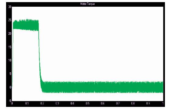
Figure 7. No Load Torque Response for Fuzzy based SVM DTC at Constant Speed 150 rad/sec
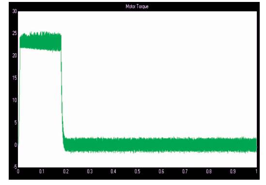
Figure 8. No Load Torque Response for Adaptive Fuzzy based SVM DTC at Constant Speed 150 rad/sec
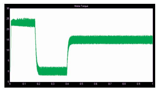
Figure 9. Load Torque Response of 15 Nm at 0.4 sec and -20 Nm at 0.75 sec for Fuzzy based SVM DTC at Constant Speed 150 rad/sec
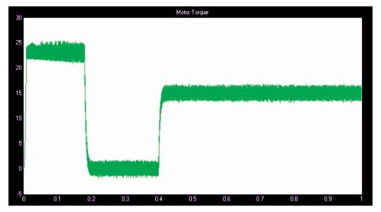
Figure 10. Load Torque Response of 15 Nm at 0.4 sec and -20 Nm at 0.75 sec for Adaptive Fuzzy based SVM DTC at Constant Speed 150 rad/sec
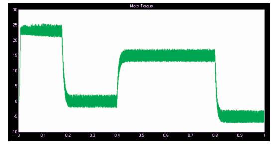
Figure 11. Load Torque Response of 15 Nm at 0.4 sec and -20 Nm at 0.8 sec for Fuzzy based SVM DTC
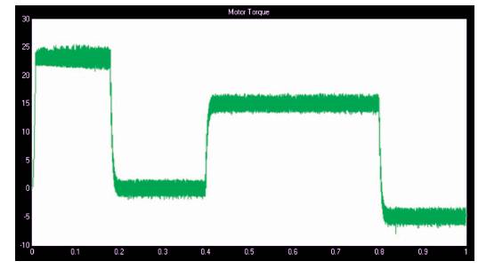
Figure 12. Load Torque Response of 15 Nm at 0.4 sec and -20 Nm at 0.8 sec for Adaptive Fuzzy based SVM DTC at Constant Speed 150 rad/sec
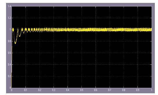
Figure 13. Flux Response for Fuzzy based SVM DTC
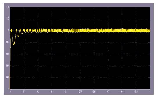
Figure 14. Flux Response for Adaptive Fuzzy based SVM DTC
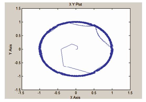
Figure 15. Flux Response for Fuzzy based SVM DTC
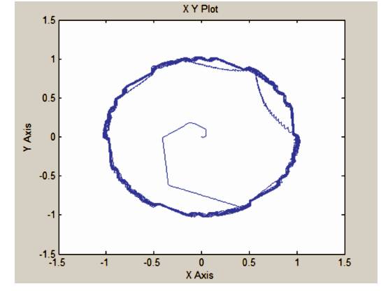
Figure 16. Stator Flux Trajectory for Adaptive Fuzzy based SVM DTC
The Space Vector Modulation (SVM) based Direct Torque Control (DTC) of Induction Motor with an Adaptive Fuzzy Logic Controller has been investigated in this paper. The performance of DTC model of induction motor with Adaptive Fuzzy Logic Controller is compared with the fuzzy logic controller. It has been observed that the torque and the stator flux ripples are significantly reduced in Adaptive Fuzzy Controller. Some other improvements observed were the reduction in flux ripple, fast torque response and increase in efficiency of the drive. Therefore, SVM-DTC method may be a better solution for general purpose IM drives in a very wide power range applications. Further, it was believed that the DTC principle will continue to play a very important role in the development of high performance AC drives.
SVM-DTC for Induction motor drive can also be recommended for various asynchronous machine drives to ensure effective transient response. Also this method can be implemented using high end digital techniques like FPGA, ASIC with better computational algorithms.