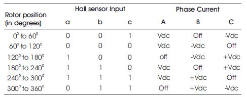
Table 1. Hall Signal Logic for Forward Rotation for BLDC Motor
This paper deals with open loop speed control of Brushless DC motor (BLDC) using Arduino UNO processor. Real-time implementation of the drive in open loop speed control has been performed in which speed of the motor depends on the input voltage given to the stator winding and it is nothing but duty cycle setting. The open loop speed control is also useful in many practical applications however, the present work mainly deals with studying the running performance of the drive without using any speed feedback arrangement. That means, the speed of the motor may vary when it is subjected to load variations and/or supply voltage variations. The validity of the proposed approach is proven through experimentation on BLDC motor using low cost Arduino UNO processor. Speed Control of BLDC motor using other microcontroller requires more hardware and increases the cost, and the availability of Arduino with versatile features motivated to develop a cost effective and reliable control with variable speed range. In the present work, an algorithm which uses the Hall sensor signals acquired from the motor is developed and the program has been written using Arduino. This program generates the firing pulses required to drive the MOSFETs of three phase fully controlled bridge converter driven by IR2101 FET drivers. Later the program which has been dumped on the Arduino and tested with the 24 V, 80 W, 1500 rpm BLDC motor which can make the motor run at constant speed ranging from 6 to 1500 rpm. The proposed hardware and the program are found to be efficient and the results are promising.
Recently developed Permanent Magnet Brushless DC (BLDC) motors have used wide application due to their power density and ease of control. Moreover, the machines have high efficiency over a wide speed range. Brushless DC motor is built in a fashion very similar to stepper motors. These often use a permanent magnet external rotor, three phases of driving coils. A BLDC motor is a rotating electric machine with a classic three phase stator like that of an induction motor and the rotor has surface-mounted permanent magnets. BLDC motors use Hall Effect sensors to sense the position of the rotor, and associated drive electronics (Bist, Member, & Singh, 2014; Bist & Singh, 2015; Singh & Singh, 2009; Singh, 1997). The coils are activated, one phase after the other, by the drive electronics as cued by the signals from either Hall Effect sensors or from the back-EMF (Electromotive Force) of the unexcited coils. In effect, they act as three-phase synchronous motors containing their own variable frequency drive electronics (Lee & Ehsani, 2003; Manual, n.d.; Salah, Ishak, & Hammadi, 2011; Sathyan, Milivojevic, Lee, Krishnamurthy, & Emadi, 2009; Yedamale, 2003). A specialized class of brushless DC motor controllers utilizes EMF feedback through the main phase connections instead of Hall Effect sensors to determine position and velocity. Recent legislation imposing efficiency standards in appliances, has forced appliance manufacturers to migrate to BLDC motors in their applications. In view of these enormous applications, researchers started developing methods for efficient use of these motors in diversified fields. BLDC motors are potentially cleaner, faster, more efficient, less noisy and more reliable. Brushless DC motors are commonly used where precise speed control is necessary, as in computer disk drives or in video cassette recorders, the spindles within CD, CD-ROM drives, and mechanisms within office products such as fans, laser printers and photocopiers.
Speed Control of BLDC motor using 8051 microcontroller requires more hardware, and the availability of Arduino with versatile features motivated to develop a cost effective and reliable control with variable speed range. Brushless motors are typically 85–90% efficient or more (higher efficiencies for a brushless electric motor, of up to 96.5%, were reported by researchers at the Tokai University in Japan in 2009), whereas DC motors with brush gear are typically 75–80% efficient (B K Bose, 2009; Chern, Liu, Tien, & Chen, 2009; Damodharan & Vasudevan, n.d.; Siwakoti & Town, 2013).
Open loop control of BLDC motor is also performed on low-cost and low power BLDC motor equipped with inbuilt hall position sensors. The hall position sensor information of forward rotation is shown in Table 1. In open loop control, Hall sensors are used. Hall Effect sensor is a transducer that varies its output voltage in response to changes in magnetic field. Hall sensors are used for proximity switching, positioning, speed detection, and current sensing applications. In its simplest form, the sensor operates as an analogue transducer, directly returning a voltage. With a known magnetic field, its distance from the Hall plate can be determined. Using groups of sensors, the relative position of the magnet can be deduced. Hall sensors are used in BLDC motors to detect the position of the permanent magnet (rotor) (Bimal K. Bose, 2002; Samoylenko & Jatskevich, 2008).
Table 1. Hall Signal Logic for Forward Rotation for BLDC Motor
The hall logic for instant “010”, means the angular position o o of BLDC motor is in between 0 and 360 . Hence the Phase-C and Phase-A of stator winding is excited through inverter and similarly for all other instants shown in Table 1. The speed of BLDC motor is depending the input voltage given to the motor and as this voltage increases, the speed of the motor increases. Each hall position instant o represents the angular position of 60 . That means, the hall signals are giving the discrete locations of rotor position in radians.
Based on the Hall sensor input to the microcontroller, the corresponding transistors are made active and current flows through two windings and the other winding is inactive and hence commutation is done electronically with the use of a microcontroller. Thus by properly exciting the corresponding winding based on the hall signal, the motor is commutated and is made to run at the desired speed. Initially irrespective of the rotor position, the windings are excited in the given sequence and once the motor starts rotating, rotor position is sensed by the Hall sensor and then the motor is excited based on the Hall signal and according to the direction of rotation of the motor.
The snapshot of hardware implementation is shown in Figure 1. The open loop speed control of drive consists of three phase; Voltage Source Inverter, BLDC motor with inbuilt hall sensors for measuring the discrete locations of rotor positions, and Arduino UNO controller board and PC. The BLDC motor as shown in Figure 2 with hall sensors is used in the present work.
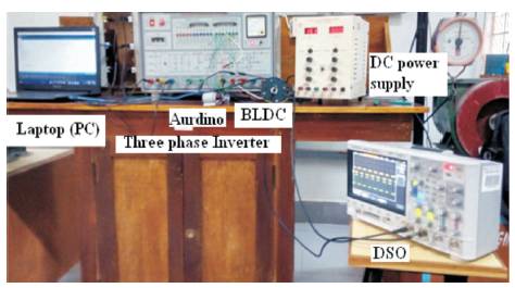
Figure 1. The Complete Hardware Setup
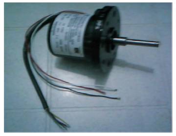
Figure 2. BLDC Motor with Hall Sensors
As the BLDC motor is an electronically commutated motor, based on position of the rotor, the stator winding is energized by switching on appropriate IGBTS of the inverter (Bimal K. Bose, 2002). First the method is tested in simulation environment and later the same is converted into Arduino based embedded code. Figure 3 shows the Arduino UNO processor used in the experimentation.
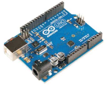
Figure 3. Arduino UNO Processor
The program developed based on above algorithm is dumped on to the Arduino device and tested on the 80 W, 4 pole, and 1500 rpm BLDC motor shown in the Figure 2.
The speed of BLDC motor varies with variation in the input voltage, when voltage increases the speed of the motor rises. First the BLDC motor is simulated in MATLAB and later validated in open loop control. In the present work, as motor is not equipped with the encoder, the corresponding gate pulses given the inverter are shown at different speeds.
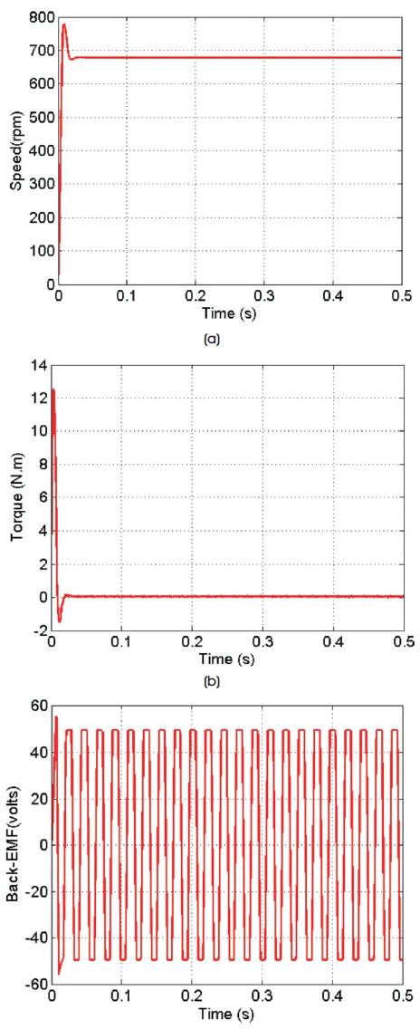
Figure 4 (a). Speed of 100 Volts, (b) Torque at 100 Volts, (c) Back-EMF at 100 Volts
The Figure 4 (a) shows the speed of the motor at 100 V, Figure 4 (b) shows the torque drawn by the motor and Figure 4 (c) shows the back-EMF waveform when motor running at 700 rpm at input voltage of 100 V. Similarly as voltage increases from 100 V to 160 V, the motor rotates at a speed of 1100 rpm for the input voltage of 160 V as shown in Figure 5 (a) and corresponding torque and back- EMF waveforms are as shown in Figures 5 (b) and 5 ©. It may observe the similar plots, when authors run the motor using the Arduino processor. Due to laboratory constraints, low cost BLDC motor without encoder is used for testing the presented method. However, the gate signals at two possible speeds at first leg of inverter are depicted in Figure 6 and Figure 7 respectively. These pulses vary based on the speed of operation and hall position information.
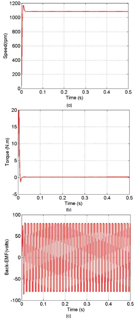
Figure 5 (a). Speed at 160 Volts, (b) Torque at 160 Volts, (c) Back-EMF at 160 Volts
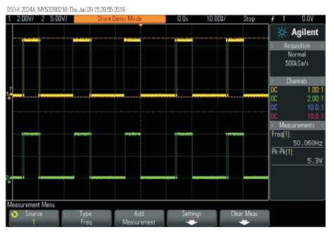
Figure 6. Gate Pulses for Low Speed
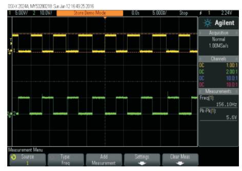
Figure 7. Gate Pulses of First Leg of Inverter at Low Speed
The present work can be recommended for household applications like fan loads, compressors, etc.
The algorithm has been programmed and dumped on to the Arduino device. The output from the Arduino are fed to IGBTs of three phase fully controlled bridge inverter with FET driver. The output of the inverter is fed to the three phase winding of the BLDC motor. The individual pulses for each IGBT is observed and open loop simulation of BLDC motor is also done using MATLAB and the results are observed. Thus the motor speed is variable ranging from 10 rpm to 1500 rpm by varying the input voltage.