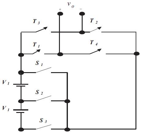
Figure 1. Proposed Symmetrical 5- Level converter
In this paper, a new multilevel converter which consists of only the seven switches rather than the conventional multilevel converter is analyzed. The various PWM techniques were included: APODPWM, COPWM and PSPWM, to generate the respective output voltage levels. It has many main advantages of lower harmonics, reductions in installation space and cost of inverter. The performance measures like Total Harmonic Distortion (THD), VRMS (fundamental) and Vpeak are evaluated for various modulation indices. This proposed multilevel converter can be analyzed and investigated through MATLAB/SIMULINK software. Finally, compared with all PWM strategies, the COPWM and PSPWM provide higher (Fundamental) RMS voltage and APOD PWM provides lower Total Harmonic Distortion (THD) .
Since the multilevel converter has been introduced in the year of 1975, it converts DC-to-AC which requires many DC sources and sums them to output a time-varying wave. Multilevel converters have a lot of advantages to offer in medium- to high-voltage range of applications. The term multilevel states that power conversions are produced by utilizing multiple small voltage levels. Small voltage step makes the multilevel inverter to withstand better voltage, fewer harmonics, lower switching losses, electromagnetic compatibility, voltage with high capability and good power quality. Multilevel converters can synthesize waveforms using more than two voltage levels. Control schemes employed in multilevel converter applications include, PWM and Line frequency control. The former allows variation of output voltage, whereas the latter does not. In general, PWM control requires the use of more than one carrier waveform to cater for the various levels. This multilevel inverter produces output voltage in stepped wave, (staircase shape) which is in sinusoidal waveform. Cascaded multilevel inverter was developed in the initial stage. In the second stage, diode clamped multilevel inverter and later flying capacitor was introduced. These three topologies utilize different mechanism to produce required output. Among these three topologies, cascaded multilevel inverter has more advantages such as simple construction using less number of switches, no need of clamping diode, flying capacitor and absence of voltage unbalance. Most of the researches are carried out in cascaded multilevel inverter configuration. Babaei et.al. (2014) present to reduce the number of independent DC voltage sources in cascaded multilevel inverter. Ajami et.al (2014) introduce cascade multi-cell multilevel converter which has advantages that reduce Total Harmonic Distortion (THD). Rathore et.al (2013) presented for obtaining optimal Pulse-Width Modulation of multilevel inverters for Low-Switching-Frequency control and for harmonic control. Rabinoici et.al (2013) presented thirteen-level H- bridge inverter operated by generic phase shifted Pulse-Width Modulation. Zixin Li et.al (2012) introduced improved pulsewidth modulation based on Modular Multilevel Converter (MMC) that can generate an output voltage with maximally 2N+1 (Where N is the submodules in the upper or lower arm of MMC) levels, which is as great as that of the Carrier Phase Shifted PWM (CPSPWM) method. Kangarlu et.al (2012) presented symmetric multilevel inverter with reduced components based on non-insulated dc voltage sources. Najafi et.al (2012) implemented a new multilevel inverter to eliminate harmonic distortion. Lezana et.al (2011) introduced hybrid multicell converter which provides no losses and high modularity. Floricau et.al (2011) presented a new multilevel converter based on stacked commutation cells with shared power devices. Kouro et.al (2010) presented recent advances and industrial applications of multilevel converters. Behera et.al (2010) introduced multilevel converter fed induction motor drive for industrial and traction drive which has less voltage stresses, harmonics, and electromagnetic interferences. Modifications are made in its inbuilt structure. In this paper, 5-level MLI is generated with 7 switches, by reducing switches from the main conventional MLI. These includes variable speed motor drives and power system applications. Recently, several multilevel inverter topologies have been developed for cascaded multilevel inverters. This can reduce the number of switches and the gate driver circuits.
Figure 1 shows the proposed topology, which has more advantages when compared with the conventional topology. To develop the Five level output for proposed system that contains seven switches and two voltage sources, this reduces one switch from its conventional system. Higher number of required Insulated Gate Bipolar Transistor (IGBTs), power diodes and driver circuits in generating a specific output level are their remarkable disadvantages. The power semiconductor switch IGBTs were used, so that it shares the bus voltage synchronously. The inverter produces output voltage in five levels:1.2Vdc,2. Vdc,3. 0,4 –Vdc, and 5-2Vdc. The multilevel converters have been developed for high voltage and high power applications. This multilevel inverter has mainly four advantages than the conventional inverter. First, the voltage stress on each switch is decreased, therefore, the rated voltage and consequently the total inverter power could be safely increased. Second, the rate of change of voltage (dv/dt) is decreased due to the lower voltage swing of each switching cycle. Third, harmonic distortion is reduced due to more output levels. Fourth, used to obtain the lower acoustic noise and the ElectroMagnetic Interference (EMI). Figure 2 shows the output voltage waveform for the symmetrical 5-level proposed converter.
Figure 1. Proposed Symmetrical 5- Level converter
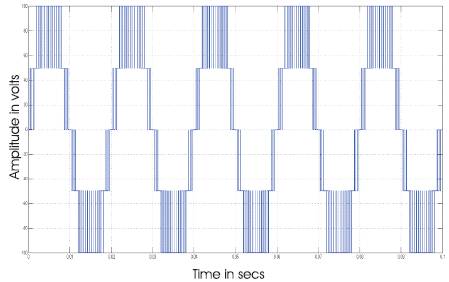
Figure 2. Five-Level Output for the Proposed Inverter
In this proposed work, a unipolar strategy is used to generate firing pulses to get five level output. For an M-level inverter used by unipolar multicarrier technique, (m-1)/2 carriers with the same peak-to-peak amplitude Ac and same frequency fc are used. The reference wave is simultaneously compared with each carrier signal, and then the active devices (switches) corresponding to that carrier are turned on, otherwise, the device is turned off. The various Pulse-Width-Modulation (PWM) techniques were used to generate their corresponding output voltage levels.
Development of this PWM technique is used to reduce the THD of the output. Increasing the switching frequency of the PWM pattern reduces the lower frequency harmonics due to its nature of moving away from the switching frequency carrier harmonics and the sideband harmonics from the fundamental frequency component . T h e modulating/reference wave of multilevel carrier based PWM strategies can be sinusoidal PWM signal. The reference wave is concerned for CFD including frequency, amplitude, phase angle of the reference wave. The following strategies are employed in this study.
In APODPWM, all the carriers are arranged in such a manner 0 that each carrier is out of phase with its neighbour by 180 . For an m-level inverter using unipolar multicarrier technique, (m-1) carriers with the same frequency fc and same peak-to-peak amplitude Ac are used. The reference waveform has amplitude Am and frequency fm and it is ended at zero level. The reference wave is continuously compared with each of the carrier signal. If the reference wave is more than a carrier signal, then the active devices corresponding to that carrier are switched on, otherwise, the devices would be switched off. The frequency ratio mf is defined in the unipolar PWM strategies as follows:
mf =fc/fm. The amplitude modulation index ma of this method is
ma= Am/nAc. Figure 3 shows the multicarrier arrangement for APODPWM method for ma = 0.8 and mf=40.
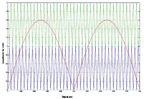
Figure 3. Carrier arrangement for APODPWM Technique
The Phase Shift Multi-Carrier Unipolar PWM technique is used in this work. Two carriers with their signals of same amplitude and frequency are shifted by 90o to one another to produce the five level inverter output voltage. The gate signals for chosen inverter can be derived directly from the PWM signals. The sinusoidal reference (i) for an odd mf, the wave has odd symmetry resulting in even and odd harmonics and (ii) for an even mf PSPWM wave has quarter symmetry resulting in odd harmonics only. Figure 4 shows the carrier arrangement for PSPWM method.
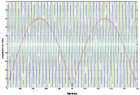
Figure 4. Carrier arrangement for PSPWM technique
For ma = 0.8 and mf = 40. The amplitude modulation index is defined for this strategy as
ma = Am/ (Ac/2).
COPWM method utilizes CFD of vertical offsets among the carriers. The main aim of COPWM is overlapping of carriers with each other at single modulating signal. For an m level inverter, m-1 carriers with the same frequency fc and same peak-to-peak amplitude Ac are disposed such that the bands they occupy overlap each other. The overlapping vertical distance between each carrier is Ac/2 in this work. The reference wave has the amplitude Am and frequency fm and it is centered in the middle of the carrier signal. The amplitude modulation index ma= Am/ (m/4) Ac. The vertical offset of carriers (unipolar) for chosen five level inverter can be illustrated in Figure 5. Figure 6 shows the carrier arrangement for COPWM strategy for ma = 0.8 and mf = 40.
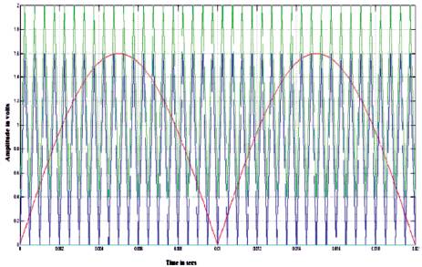
Figure 5. Carrier arrangement for COPWM technique
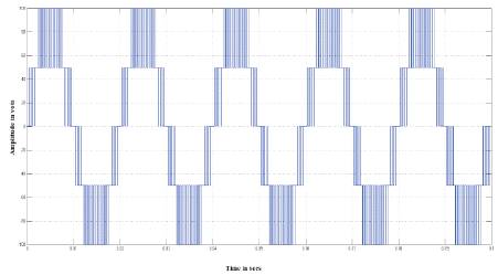
Figure 6. Output Voltage generated by APODPWM technique
In this paper, mf= 40 and ma= is varied from 0.6 to 1, mf is chosen as 40 for the following reasons.
The cascaded five level inverter can be modeled in SIMULINK model by using power system block set. Switching signals for CMLI are developed using unipolar PWM techniques which are stated earlier. The simulation is performed for different values of ma ranging from 0.6-1. The corresponding % THD values, Vrms of fundamental, DC component to fundamental and peak amplitude voltage Vpeak of inverter output for same modulation indices corresponding to FFT plots are shown in Tables 1, 2 and 3. Figures 6-11 show the simulated output voltage of CMLI and corresponding FFT plots with above strategies but for only one sample value of ma = 0.8. Figure 6 shows the five level output voltage generated by APODPWM strategy and its FFT plot is shown in Figure 7. Figure 8 shows the five level output voltage generated by PSPWM strategy and its FFT plot is shown in Figure 9. Figure 9 Shows the PSPWM strategy, which does not have any significant amount of harmonic energy. Figure 10 shows the five level output voltage generated by COPWM strategy and its FFT plot is shown in Figure 11. From Figure 11 it is noticed that the COPWM strategy produces significant 3rd and 38th harmonic energy. The following parameter values are used for simulation:
Vdc = 50V and R (load) = 10 ohms.
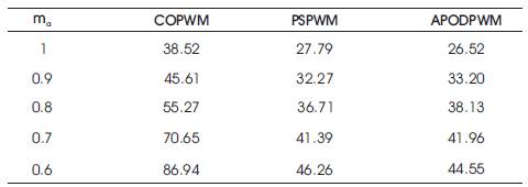
Table 1. % THD for different modulation indices with sinusoidal reference.
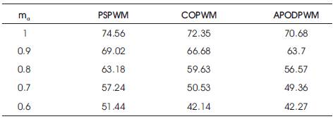
Table 2. Vrms for different modulation indices with sinusoidal reference
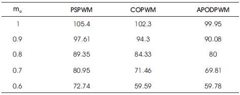
Table 3. Vpeak for different modulation indices with sinusoidal reference
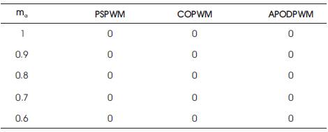
Table 4. DC component for different modulation indices with sinusoidal reference
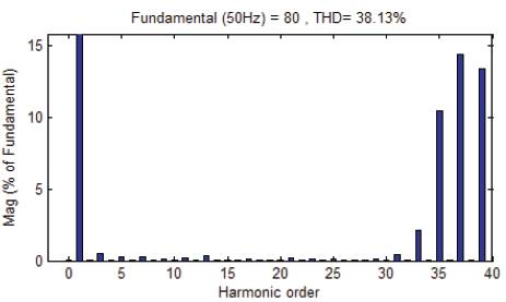
Figure 7. FFT plot for output voltage of APODPWM technique.
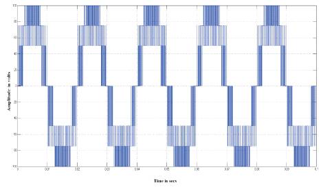
Figure 8. Output voltage generated by PSPWM technique.
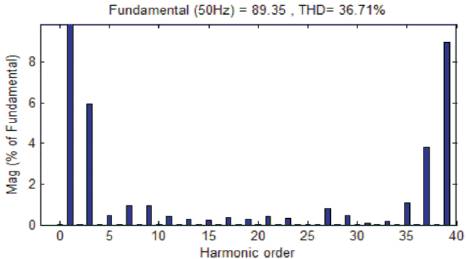
Figure 9. FFT plot for output voltage of PSPWM technique.
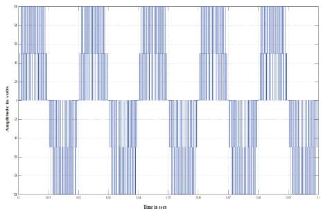
Figure 10. Output voltage generated by COPWM technique.
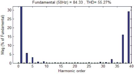
Figure 11. FFT plot for output voltage of COPWM technique.
The 5-level CMLI using seven switches is successfully introduced while the simulation is done by MATLAB/ SIMULINK and has observed a clear stepped 5-level waveform. Main finding is that the APODPWM strategy has lesser %THD while compared with all other PWM strategies. The PSDPWM strategy produces higher fundamental RMS output voltage. The new design is simple in its outlook and only few components were used. The novel 5-level multilevel inverter has lower THD compared to conventional symmetric and asymmetric topologies.