[1]
The use of Induction motors has increased tremendously, since the day of its invention. They are being used as actuators in various industrial processes, robotics, house appliances and other similar applications. The reason for increasing popularity day by day can be primarily attributed to its robust construction, simplicity in design and cost of effectiveness. This paper presents a methodology for implementation of a rule-based fuzzy logic controller applied to a closed loop Volts/Hz speed control of induction motor. The Induction motor is modelled using a dq axis theory. The designed Fuzzy Logic Controller's performance is weighed and is compared with that of a PI controller. The system has been simulated in MATLAB/SIMULINK and the results have been presented. The results obtained by using a conventional PI controller and the designed Fuzzy Logic Controller have been compared.
The Induction machine is an important class of electric machines which finds wide applicability as a motor in industry and they are manufactured in large numbers. Almost 90% of the mechanical power used in the industry is provided by 3-phase induction motors. It is substantially a constant-speed motor with a shunt characteristic; a few percent speed drop from no-load to full load. It is a singlyfed motor unlike the synchronous motor which requires ac supply on the stator side and dc excitation on the rotor. The torque developed in this motor has its origin in current induction in the rotor which is only possible at nonsynchronous speed, hence the name asynchronous machine. Speed control is one of the various application imposed constraints for the choice of a motor (Menghal & Jaya Laxmi,2014) . Out of all the speed control mechanisms, the volts/hertz control scheme is very popular because it provides a wide range of speed control with good running and transient performance (Chan & Shi, 2011;Krause, 2000). This control mechanism is referred to as scalar control mode. Here both the input and output commands are speed, unlike the vector control mode where it is torque/flux and reference current, respectively. The field of Power Electronics has contributed immensely in the form of voltage-frequency converters which has made it possible to vary the speed over a wide range. However, the highly non-linear nature of the induction motor control dynamics demands strenuous control algorithms for the control of speed. The conventional controller types that are used for the aforementioned purpose are may be numeric or neural or fuzzy. The only problem associated with use of conventional controllers in speed control of induction motors is the complexity in design arising due to the nonlinearity of Induction Motor dynamics(Menghal & Jaya Laxmi,2013) . The conventional controllers have to linearize the non-linear systems in order to calculate the parameters. To overcome the complexities of the conventional controllers, fuzzy Control has been implemented in many motor control applications. In the last three decades, fuzzy control has gained much popularity owing to its knowledge based algorithm, better non-linearity handling features and independence of plant modelling. (P. M.Menghal, A Jaya Laxmi and N.Mukhesh;2014) The Fuzzy Logic Controller (FLC) owes its popularity to linguistic control. Fuzzy logic basically tries to replicate the human thought process in its control algorithm. The FLC has thereby proven to be very beneficial in the industries as it has the proficiency to provide complex non-linear control to even the uncertain nonlinear systems (Rajesh Kumar, R. A. Gupta Rajesh S. Surjuse;2009). In addition to the aforementioned attributes, a fuzzy logic controller also makes good performance in terms of stability, precision, reliability and rapidity achievable. Performance of fuzzy logic based controllers is compared with that of the conventional proportional integral controller modulation (Uddin & Haffez, 2012; Uddin &Wen, 2007).
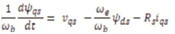
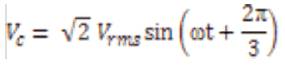
The induction motors’ dynamic behavior can be expressed by voltage and torque which are time varying. The differential equations that belong to dynamic analysis of induction motor are so sophisticated. Then with the change of variables, the complexity of these equations decrease through movement from poly phase winding to two phase winding (q-d). In other words, the stator and rotor variables like voltage, current and flux linkages of an induction machine are transferred to another reference model which remains stationary (P.C. Krause,2000; Ned Mohan;2001).
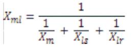
Figure 1 stator inductance is the sum of the stator leakage inductance and magnetizing inductance (Lls = Ls + Lm ), and the rotor inductance is the sum of the rotor leakage inductance and magnetizing inductance (Llr = Lr + Lm). From the equivalent circuit of the induction motor in d-q frame, the model equations are derived. The flux linkages can be achieved as
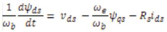
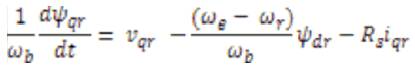
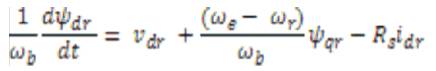
By substituting the values of flux linkages in the above equations, the following current equations are obtained as
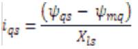
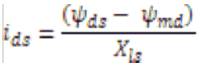
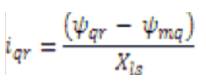
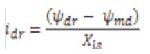
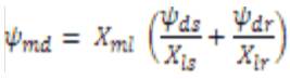
Where ψmq and ψmd are the flux linkages over Lm in the q and d axes. The flux equations are written as follows

In the above equations, the speed ωr is related to the torque by the following mechanical dynamic equation as
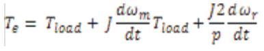
Then ωr is achievable from above equation, where
p- number of poles.
J- moment of inertia (kg/m2).
In the above section, dynamic model of an induction motor is expressed. The model constructed according to the equations has been simulated by using MATLAB/SIMULINK as shown in Figure 2 in conventional mode of operation of induction motor. A 3 phase source is applied to conventional model of an induction motor and the equations are given by
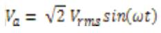
By using Parks Transformation, voltages are transformed to two phases in the d-q axes, and applied to induction motor. In order to obtain the stator and rotor currents of induction motor in two phases, Inverse park transformation is applied in the last stage. (K.L.Shi, T.F.Chan, Y. K. Wong and S. L .HO ;1999) .
A PI controller responds to an error signal in a closed control loop and attempts to adjust the controlled quantity to achieve the desired system response. The controlled parameter can be any measurable system quantity such as speed, torque or flux. The benefit of the PI controller is that it can be adjusted empirically by adjusting one or more gain values and observing the change in system response. It is assumed that the controller is executed frequently enough so that the system can be properly controlled. The error signal is formed by subtracting the desired setting of the parameter to be controlled from the actual measured value of that parameter. The Integral (I) term of the controller is used to eliminate small steady state errors. The I term calculates a continuous running total of the error signal. Therefore, a small steady state error accumulates into a large error value over time. This accumulated error signal is multiplied by an I gain factor and the output term becomes for the PI controller. In the PI block shown in Figure 3, Speed is converted into frequency, error is minimized between reference speed and measured speed and output frequency is given to the voltage source inverter which converts frequency into three phase voltage signal and these signals are given to the induction motor which controls the speed and torque (Mouloud Azzedine Denai and Sid Ahmed Attia,2002).
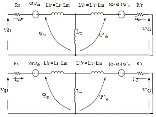
Figure 1. d-q model of Induction motor
Figure 2. Conventional simulation model
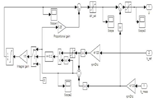
Figure 3. Structure of PI Controller
One of the reasons for the popularity of Fuzzy Logic Controllers is, its logical resemblance to a human operator. It operates on the foundations of a knowledge base which in turn rely upon the various if then rules, similar to a human operator. Unlike other control strategies, this is simpler as there is no complex mathematical knowledge required. The FLC requires only a qualitative knowledge of the system thereby making the controller not only easy to use, but also easy to design. (P M Menghal, A Jaya Laxmi;2012; 2014) . The inputs to a Fuzzy Logic Controller are then processed with the help of linguistic variables which in turn are defined with the aid of membership functions. The membership functions are chosen in such a manner that they cover the whole of the universe of discourse (M Nasir Uddin, Tawfik S. Radwan and Azizur Rahman;2002) . To avoid any discontinuity with respect to minor changes in the inputs, the adjacent fuzzy sets must overlap each other. Because of a small time constant in Fuzzy Logic Controllers, this criterion is very important in the design of the same. There are basically three essential segments in Fuzzy Logic Controller viz. Fuzzification block or Fuzzifier, Inference System and Defuzzification block or Defuzzifier. Figure 4. shows the Structure Fuzzy logic controller.
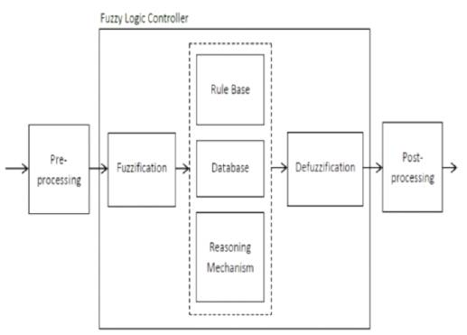
Figure 4. Structure Fuzzy logic controller
The speed of induction motor is adjusted by the fuzzy controller. In Table 1, the fuzzy rules decision implemented into the controller are given. The conventional simulated induction motor model as shown in Figure 2 is modified by adding Fuzzy controller and is shown in Figure 5. Speed output terminal of induction motor is applied as an input to fuzzy controller, and in the initial start of induction motor the error is maximum, so according to fuzzy rules, FC produces a crisp value. (M. Nasir Uddin, Hao Wen;2007). Then this value will change the frequency of sine wave in the speed controller. The sine wave is then compared with triangular waveform to generate the firing signals of IGBTs (Insulated- Gate Bipolar Transistor) in the PWM inverters. The frequency of these firing signals also gradually changes, thus increasing the frequency of applied voltage to Induction Motor. As discussed earlier, the crisp value obtained from Fuzzy Logic Controller is used to change the frequency of gating signals of PWM inverter. Thus the output AC signals obtained will be variable frequency sine waves. The sine wave is generated with amplitude, phase and frequency which are supplied through a GUI. (Bimal K. Bose;2007) . Then the clock signal which is sampling time of simulation is divided by crisp value which is obtained from FLC. So by placing three sine waves with different phases, one can compare them with triangular waveform and generate necessary gating signals of PWM inverter. So at the first sampling point, the speed is zero and error is maximum. (Besir Dandil, Muammer Gokbulut Fikrat Ata; 2005).
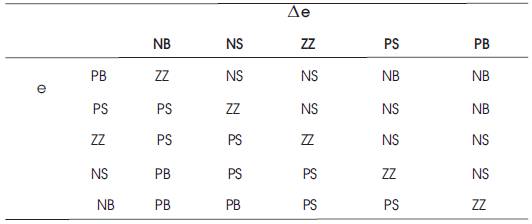
Table 1. Modified Fuzzy Rule Decision
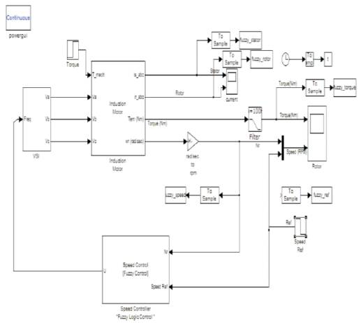
Figure 5. Fuzzy control Induction motor model
MFG block is designed to generate a membership function and outputs the value of suitable grade. This block can be tuned easily to obtain any piece-wise linear characteristics such as: triangular, trapezoidal and singleton forms. Fuzzy set can be represented as one of {NB, NM, NS, ZE, PS, PM, PB}using the MFG block. In Figure 6, Figure 7 and Figure 8 the structure of membership function generator for error, change in error, outputs is shown respectively. Fuzzification is done on the Error and change in error and input crisp value is fuzzified and the values of membership function blocks are applied through GUIs. (P M Menghal, A Jaya Laxmi;2013) .
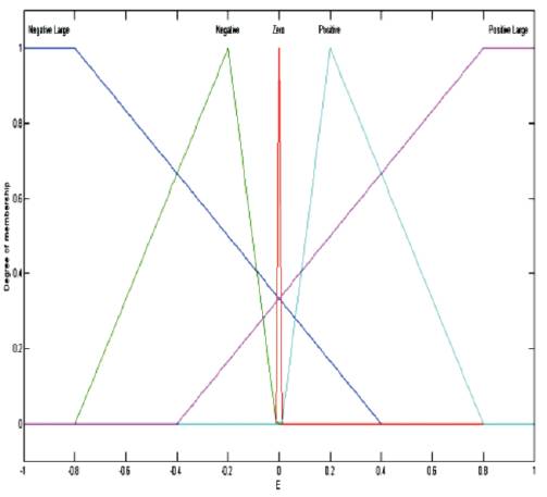
Figure 6. Structure of Membership Function generator for error
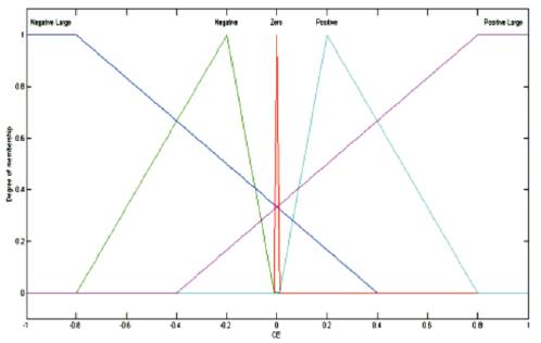
Figure 7. Fuzzification is Change in error
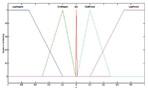
Figure 8. Output of Fuzzy
Surface Plot: A phase plot is a plot of a time-dependent variable against its own time derivative. The control surface is a plot of change in the error against error, with the control signal along the third axis, and therefore forms a surface. With two inputs and one output, the rule base mapping is the relationship between error and change in error on the premise side, and control action on the conclusion side as portrayed in the control surface. (M Nasir Uddin, Tawfik S. Radwan et al.;2002) . These are smooth trapezoids, built from segments of cosine functions. When the error is near zero, a disturbance will increase the magnitude of the control signal, but when the error reaches a certain level, a further disturbance causes little or no increase of the control signal. The same can be said for the change in error. The surface has a stepper slope, higher gain, near the centre than the linear surface. The surface block of non linear system is shown in Figure 9.

Figure 9. Surface plot
Modeling and simulation of Induction motor in conventional and fuzzy are done on MATLAB/SIMULINK. A complete simulation model for inverter fed induction motor drive incorporating the proposed FLC has been developed. The dynamic performance of the proposed FLC based induction motor drive is investigated. The proposed FLC controller proved to be more superior as compared with conventional PI speed controller based IM drive. The results of simulation for induction motor with its characteristics are listed in Appendix 'A'. Figure 10 (a,b,c) and Figure 11 (a,b,c) show the speed response and the torque–speed characteristics of conventional PI and FLC controller respectively. It can be seen from Figure 10(c) that by using the Fuzzy Logic Controller, the overshoots are lesser as compared to the case when the PI Controller is used. The settling time is also less in case of the Fuzzy Logic Controller, but the rise time is larger. The Fuzzy Logic Controller, however, portraits a better response when the reference speed is changed (either decreased or increased with respect to the base speed). It tends to approach the new reference speed faster and has, comparatively, a very low overshoot. The Fuzzy Logic Controller on the other way attains a steady state. Even though this attained speed is not exactly equal to the new reference speed, it is very much close to it. The torque plots in Figure 11(c) shows that while using the Fuzzy Logic Controller, oscillations occur during starting while the PI controller doesn't show any such characteristic. This is because the Fuzzy Logic Controller is based on random knowledge of data. The machine provides a desirable response after some time as the controller first has to learn from or adjust according to the data provided by the user.
Induction motor under no load and load of 10Nm is considered. Parameters like rise time, settling time, overshoot and peak values are tabularized in Table 2 and Table 3. Figure 12(a),(b) shows the speed response of Induction motor using PI and Fuzzy logic controller. From the output response we observe that, initially speed increases slowly from 0 RPM to 1710 RPM and after reaching the step time 0.8, the speed decreases from 1710 RPM to 1200 RPM. Figure 13(a) and (b) shows speed and torque response of PI and Fuzzy Logic Controller at load (10Nm) condition. Figure 14 (a)&(b) and Figure 15 (a, b) show the stator and rotor currents of PI and Fuzzy under No-load and Load condition.
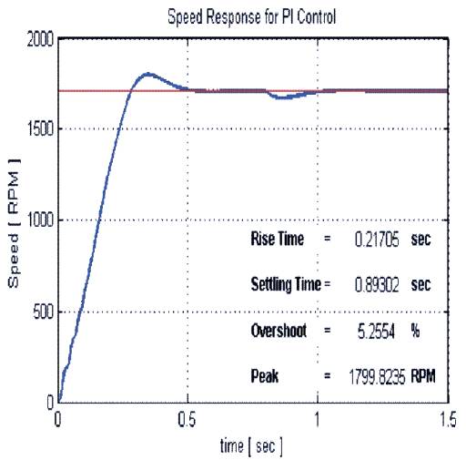
Figure 10(a). Speed response of PI controller

Figure 10(b). Speed response of Fuzzy logic controller

Figure 10(c). Speed response of PI and Fuzzy logic controller
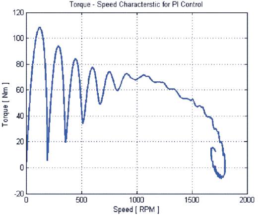
Figure 11(a). Speed response of PI and Fuzzy logic controller
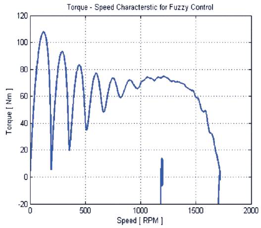
Figure 11(b). Speed response of PI and Fuzzy logic controller
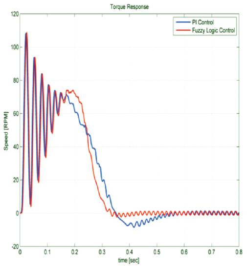
Figure 11(c). Torque-Speed characteristics of PI and Fuzzy logic controller
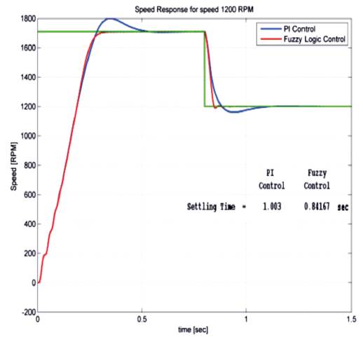
Figure 12(a). Speed response of PI and Fuzzy at 1200 RPM
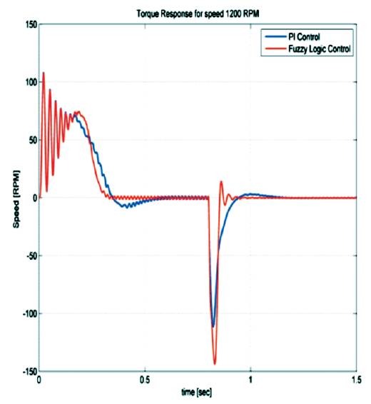
Figure 12(b). Torque response of PI and Fuzzy at 1200 RPM
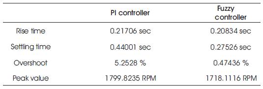
Table 2. Speed Comparision between Conventional and FLC Under No Load Condition
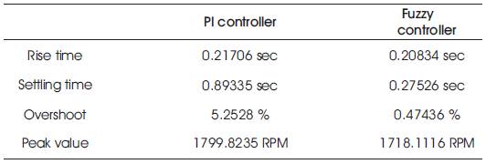
Table 3. Speed Comparision between Conventional and FLC at Load (10nm) Condition
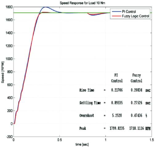
Figure 13(a). Speed response of PI and Fuzzy at load (10Nm)
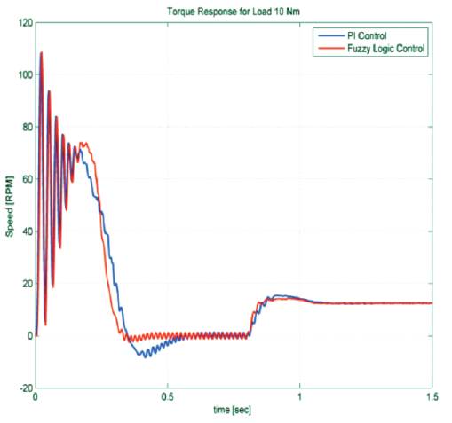
Figure 13(b). Torque response of PI and Fuzzy at load (10Nm)
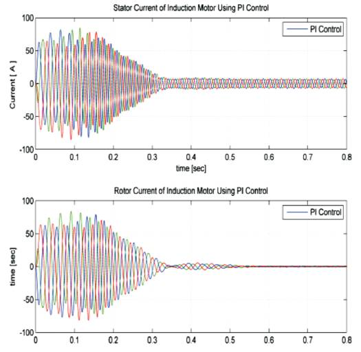
Figure 14(a). Stator and rotor currents of Induction motor using PI at no-load
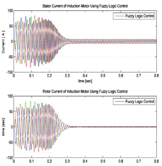
Figure 14(b). Stator and rotor currents of Induction motor using Fuzzy at no-load
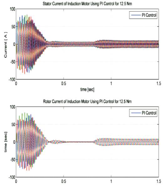
Figure 15(a). Stator and rotor currents of Induction motor using PI under load (12.5Nm)
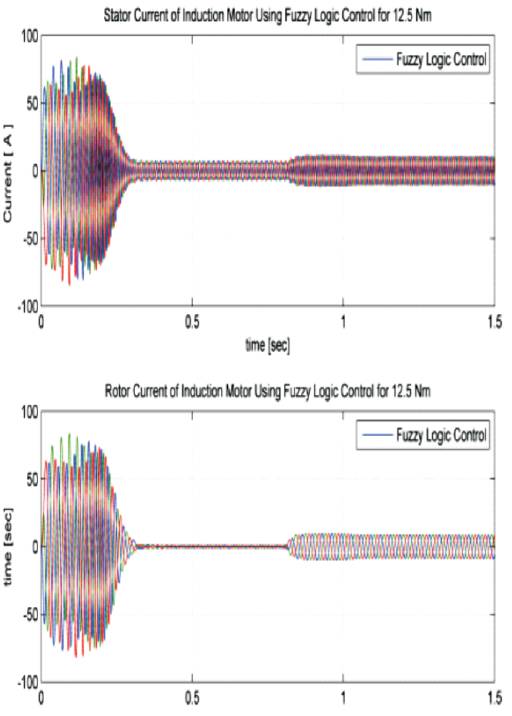
Figure 15(b). Stator and rotor currents of Induction motor using Fuzzy under load (12.5Nm)
In this paper, comparison of simulation results of the induction motor are presented with different types of controller such as conventional and fuzzy logic controller. From the speed waveforms, it is observed that with fuzzy controller, the rise time decreases drastically, in a manner in which the frequency of sine waves are changing according to the percentage of error from favorite speed. The frequency of these firing signals also gradually changes, thus increasing the frequency of applied voltage to Induction Motor. According to the direct relation of induction motor speed and frequency of supplied voltage, the speed will also increase. With results obtained from simulation, it is clear that operation condition of induction motor, fuzzy controller has better performance than the conventional controller.
The following parameters of the induction motor are chosen for the simulation studies
V = 220 f = 60 HP = 3 Rs = 0.435
Rr = 0.816 Xls = 0.75 Xlr = 0.754 Xm = 26.13
p = 4 J = 0.089 rpm = 1710