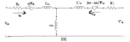
Figure 1(a): q-axis Diagram of Induction Motor,
Squirrel Cage Induction Motors are the widely used motors in Industries due to its simple construction, robust design and low operational costs. The utilization of Squirrel Cage Induction Motors with electronic inverters present greater advantages on cost and energy efficiency, compared with other industrial solutions for varying speed applications. The induction motor with inverters gives excellent speed torque control characteristics. In this paper, a transient behavior of a 3HP, 4 Pole, 50 Hz, 1430 rpm Squirrel Cage Induction Motor has been analyzed. The open and closed loop induction motor is fed Into Pulse Width modulation (PWM) inverter model developed in the recent Matlab/Simulink environment. The Sinusoidal Pulse Width Modulation (SPWM) variable speed drives are increasing these days and used in various industrial applications with superior performance. Since the developments in power electronics and semiconductor technology have led to improvements in power electronic systems, consequently variable voltage and variable frequency control is obtained by Voltage Source Inverters (VSC). In Induction motor drives, SPWM inverters make it possible to control both frequency and magnitude of the voltage and current applied to the motor. As a result, PWM inverter- powered motor drives are more variable and offer in a wide range better efficiency and higher performance when compared to the fixed frequency motor drives. These inverter fed-motors are recently gathering great popularity for multi-megawatt industrial drive applications. In this present paper, the open and closed loop induction motor fed with PWM inverter model has been discussed and focused on transient characteristics of the motor. The direct torque control method is used to control the induction motor in closed loop.
Induction motors are the most widely used motors for appliances, Industrial Control and automation; hence, they are often called the Workhorse of the Motion Industry. When power is supplied to an Induction Motor at the recommended specifications, it runs at its rated speed [1- 2]. However, many applications need to have variable speed operations. For example, a Washing Machine may use different speeds for each wash cycle. Historically, mechanical gear systems were used to obtain variable speeds. Recently, electronic power and control systems such as PWM inverter have matured to allow these components to be used for motor control in the place of mechanical gears [3-4]. These electronics devices such as PWM not only control the motor's speed, but can also improve the motor's dynamic and steady state characteristics. In addition, electronics devices can reduce the system's average power consumption and noise generation of the motor. The utilization of static frequency inverters comprehends currently the most efficient method to control the speed of induction motors. Voltage Source Inverters (VSI) transform a constant frequency constant amplitude voltage into a variable (controllable) frequency-variable (controllable) amplitude voltage. The variation of the power frequency supplied to the motor leads the variation of the rotation of field speed, which modifies the mechanical speed of the machine [5-6].
The Induction Motor may be used in some important applications in the place of D.C. machines. The most important feature which declares induction motor as a tough competitor to D.C. machines in the drives field is that its cost per KVA is approximately one fifty of its counterpart and it possesses higher suitability in hostile environment [1,4].
Since the Induction Machine modelling has continuously attracted the attention of researchers not only because such machines are made and used in largest number of applications, but also due to their varied modes of operation, both under steady state and dynamic states. In Electric Drive System elements, such machines are a part of the control system elements, which is to be controlled by the dynamic behavior of Induction Motor (IM) and then the dynamic model of IM has to be considered. The dynamic model considers the instantaneous effects of varying voltage/currents, stator frequency and torque disturbance [2, 7-11]. In this paper, the dynamic open and closed loop IM fed PWM inverter mode lis derived by using d and q variables with PWM inverter in a stationary rotating reference frame. From the simulation models the transient behavior of the motor are observed by the stator current, electromagnetic torque and rotor speed waveforms.
In Electrical Engineering, direct-quadrature-zero (or dq0) transformation or zero-direct-quadrature (or 0dq) transformation is used as a Mathematical Transformation to simplify the analysis of three-phase circuits. In this case of balanced three-phase circuits, application of the dq0 transform reduces the three AC quantities to the two DC quantities. Simplified calculations can be carried out on these imaginary DC quantities before performing the inverse transform to recover the actual three-phase AC results. It is often used in order to simplify the analysis of three-phase induction machines or to simplify calculations for the control of three-phase inverters.
The simulink model and corresponding mathematical analysis of the models are as shown in Figure 1(a) and Figure 1(b).
Figure 1(a): q-axis Diagram of Induction Motor,
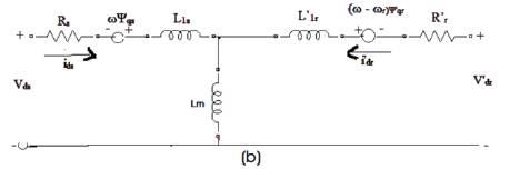
Figure 1(b): d-axis Diagram of Induction Motor
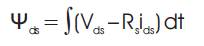
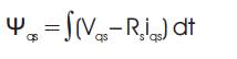
The stator voltage on the q-axis and d-axis are given in equation 1 and 2. Equations 1 to 7 come into the category of Electrical system.


The rotor voltage on q-axis and d-axis are given in equation 3 and 4.


The Electromagnetic Torque is given in equation
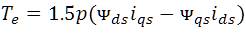
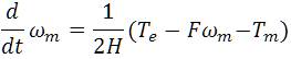
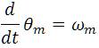
The equations for the Mechanical System are as shown Below
All machine block parameters are shown in Table 1.
The quadrature axis d-axis and q-axis are obtained to form abc to dq conversion.
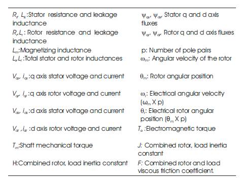
Table 1. Machine Block Parameters (All quantities are referred to the stator side)
The following relationships describe the abc-to-dq Reference Frame transformations applied to the Induction Machine phase-to-phase voltages .
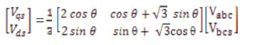
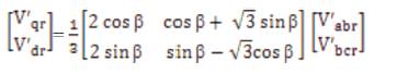
In the preceding equations, θ is the angular position of the reference frame, while β = θ - θr is the difference between the position of the electrical reference frame and the position of the rotor. Because the machine windings are connected in a three-wire Y configuration, there is no homopolar (0) component. This also justifies the fact that two line-to-line input voltages are used inside the model instead of three line-to-neutral voltages.
The following relationships describe the dq-to-abc reference frame transformations applied to the Induction Machine phase currents.
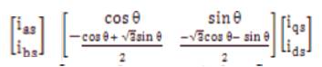
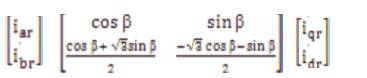
Where ias , ibs , ics are the stator currents in different phases. íar , ibr ,ícr are the rotor currents in different phases.
Variable speed controls of AC electrical machines make use of force-commutated electronic switches such as IGBTs, MOSFETs, and GTOs. Induction motors fed by Pulse Width Modulation (PWM) Voltage Sourced Converters (VSC) are now a days gradually replacing the DC motors and thyristor bridges. With PWM, combined with modern control techniques such as field-oriented control or direct torque control, it can be obtained by the same flexibility in speed and torque control with DC machines. This is because, the IGBTs are having superior characteristics rather than other power electronics switches which are having the medium power applications. Therefore, in the present section, we have developed an open and closed loop induction motor fed PWM inverter model with IGBT switch in the Matlab/Simulink.
This Squirrel cage Induction machine block can be operated in generator as well as in motor mode. It depends upon the sign of mechanical torque(Tm ). where Tm is positive as shown in Figure. 2. The machine acts as a motor and if Tm is negative it acts as generator. The applied full load nominal constant mechanical torque at the machine's shaft is 15 Nm. The simulink output block has one output but it contains 21 signals. The authors can demultiplex these signals by the Bus Selector block provided by the simulink library.
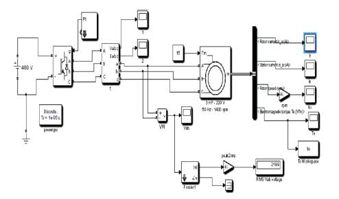
Figure 2. Open Loop Simulink Model of Squirrel Cage Induction Motor Model
An open loop three-phase squirrel induction motor rated 3 HP, 220 V, 1430 rpm is fed by a sinusoidal PWM inverter considered as shown in Figure. 2. The base frequency of the sinusoidal reference wave is 50 Hz while the triangular carrier wave's frequency is set to 1650 Hz. This corresponds to a frequency modulation factor m off 33(50Hz×33=1650 Hz). The Maximum time step has been limited to 10 μs. This is required due to the relatively high switching frequency (1650 Hz) of the inverter. It is recommended in [1] that mf is an odd multiple of three and that the value should be as high as possible. The PWM inverter is built entirely with standard Simulink blocks.
The Machine's rotor is short-circuited. Its stator leakage inductance Lls is set to twice its actual value to simulate the effect of a smoothing reactor placed between the inverter and the machine. The motor is started from standstill condition. The speed set point is set to 1430 rpm under full load condition. This speed is reached after 0.4 s. It has been observed that the rotor and stator currents are quite "noisy," despite the use of a smoothing reactor. The noise introduced by the PWM inverter is also observed in the electromagnetic torque waveform Te. However, the motor's inertia prevents this noise from appearing in the motor's speed waveform.
The reference frame is used to convert input voltages (abc reference frame) to the dq reference frame, and output currents (dq reference frame) to the abc reference frame. The authors have choose among the following reference Frame transformations
In this case the authors have considered stationary reference frame. For the Stationary Reference Frame, the value of rotor angle is set to 0 and the value of β is set to -θr . The complete mathematical modeling and corresponding equations of the model have already been explained. The choice of reference frame affects the waveforms of all dq variables. It also affects the simulation speed and accuracy of the results. The following guidelines are suggested in [1].
The descriptions of the used squirrel cage induction motor and parameters of the equivalent circuits elements are used as shown in Table 2.
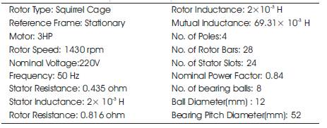
Table 2. Motor Description and Equivalent Parameters
The Parameters of IGBT/Diodes block is as shown in Table 3. The snubber circuit is integral to the universal bridge dialog box in the Matlab/Simulink as the C capacitor value of the s snubber is set to be infinite (short- circuit). It means they used the purely resistive snubber. Generally, IGBT bridges do not use snubbers; however, because of each nonlinear element in the Matlab/Simulink, it is modeled as a current source. Therefore, the authors have to provide a parallel path across each IGBT in order to allow the connection to an inductive circuit (stator of the induction motor). The high value of the snubber does not affect the circuit performance. A pulse generator is used to control the inverter bridge.
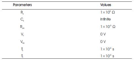
Table 3. Parameters of IGBT/Diodes Block
The efficient and common method is used for generating the PWM pulses. For generating the PWM pulses comparison of the output voltage to synthesize (50 Hz in this case) with a triangular wave at the switching frequency 1650 Hz (in this case) is carried out. This method is implemented in the Discrete 3- phase PWM pulse generator block in the Matlab/Simulink. The line-to-line RMS output voltage is a function of the DC input voltage and of the modulation index m as given by the following equation:
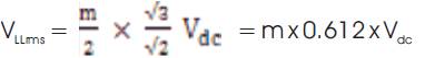
Therefore, DC voltage of 400 V and a modulation factor of 0.90 yields the 220 Vrms output line-to-line voltage, which is the nominal voltage of the induction motor.
The fundamental component (50 Hz) is measured by the discrete Fourier block which is embedded in the chopped Vab voltage and in the phase current.
The simulation results in symmetrical or balanced supply (or called healthy mode) motor condition of the motor are as shown in Figure. 3. Three motor signatures are considered, those are stator current, rotor speed and electromagnetic torque. In the healthy mode of the motor the slip is set at 1(s=1) and input mechanical torque is 15 N-m. It is observed from the obtained results that all the motor signatures are reached in the steady state condition after 0.4 seconds. The motor's speed is reached (i.e. 1430 rpm) in the steady state of after 0.4 sec.
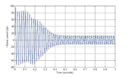
Figure 3. Symmetrical Condition of the Motor, (a) Stator Current
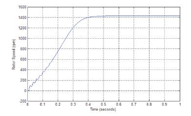
Figure 3. Symmetrical Condition of the Motor (b) Rotor Speed
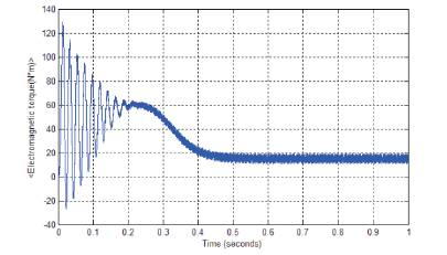
Figure 3. Symmetrical Condition of the Motor(c) Electromagnetic Torque
It has been observed that in the starting of the motor, the first peak of the stator current and electromagnetic torque waveforms have the highest amplitude when it is decreased and reached in the stable condition. The rotor speed is controlled by V/f control method of the induction motor. The model is simulated for 1 sec for clear visualization of transient characteristics. Therefore, transient characteristics of the motor may be clearly observed and analysed.
The motor starts and reaches its steady state speed 1430 rpm, after 0.4 sec. On starting, the magnitude of the 50 Hz current reaches 96 A peak( 68 A RMS) whereas its steady state value is 12.25 A( 8.66 A RMS). Therefore, the magnitude of the 50 Hz voltage contained in the chopped wave stays at 220
The electromagnetic torque waveform shows that it is reached in the stable condition after 0.4 sec. It has also been observed that there are strong oscillations of the electromagnetic torque at the start. If it is zoomed in on the torque in steady state, a noisy signal will be observed with a mean value 15 N.m, corresponding to the load torque at nominal speed .
If the authors can zoom on the three motor currents, they can observe that all the harmonics (multiple of the 1650 Hz switching frequency) are filtered by the stator inductance, hence they can say that the 50 Hz component is dominant.
The induction motor fed PWM inverter can control the large amount of speed of the motor. The 3 HP, 4 pole, 50 Hz motor's speed can be controlled efficiently by the V/f control method. The speed can vary from 1953 rpm to 189 rpm by changing the frequency of the inverter.
The rotor speed, electromagnetic torque and stator current for various frequencies have been carried out. The rotor speed waveform for 20 Hz and 70 Hz are as shown in Figures 4-9.
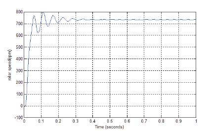
Figure 4. Rotor Speed for f=25 Hz
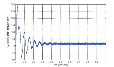
Figure 5. Electromagnetic Torque for f=25 Hz
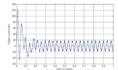
Figure 6. Stator Current for f=25 Hz
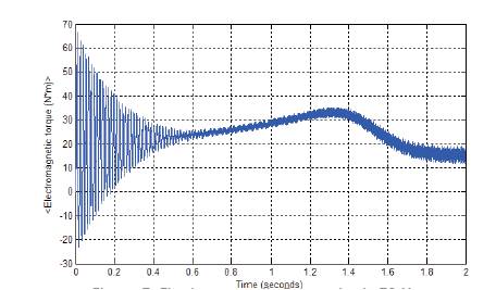
Figure 7. Electromagnetic Torque for f=70 Hz
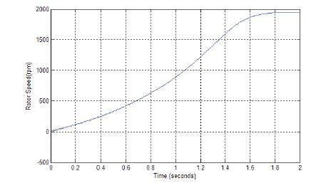
Figure 8. Rotor Speed for f=70 Hz
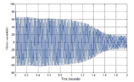
Figure 9. Stator Current for f=70 Hz
The wide range of rotor speed is varied by the inverter frequency. It has been observed from the above waveforms that when the motor frequency is 50 Hz. For this the rotor moves with the nominal speed i.e. 1430 rpm at this rated frequency.
When inverter frequency is increased or decreased when compared to the rated frequency, the large variation in the rotor speed has been taken place. The frequency variation of the inverter is considered from 70 Hz to 5 Hz. It can observed from Table 4, that the inverter frequency is able to control the speed up to 1953 rpm to 189 rpm. Therefore, they can say that a wide range of speed control is possible through this inverter fed with open loop induction motor model by the V/f control strategy efficiently. The same speed variation can be achieved through the variation of power also. Therefore, the motor power will be varied from 2.95 HP to 0.15 HP. So, the authors can say that an efficient V/f control has been successfully implemented in this model.
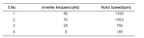
Table 4. Variation in the Rotor Speed with Inverter Frequency
The Transient Variations in the motor signatures are as shown in Table 5. The transient analysis has been done only for variations at first maximum peak of the waveforms for stator current, rotor speed and electromagnetic torque for various frequencies. When frequency is 50 Hz, it will get the rated values of the motor. When the frequency of the inverter is increased or decreased, the motor parameters will be changed correspondingly, as shown in Table 5. When the inverter frequency is 50 Hz, the stator current, rotor speed and electromagnetic torque are 95.67A, 1430 rpm, 129.26 N.m respectively. These are high values in the first peak because high switching frequency is used with inverter. For other frequencies the variations in the motor signatures are as shown in the corresponding Table 5.
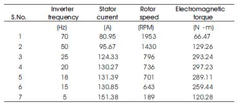
Table. 5 Transient Variation in the Motor Signatures
It has been observed in Table 5, that upto 20 Hz frequency, the electromagnetic torque first transient peak is being increased upto 290 N.m torque. If the authors further decreases the frequency, the maximum peak electromagnetic torque is being decreased as shown in Figure. 10 and Figure. 11. Therefore, they can say that the induction motor signature variations in the transient conditions are completely controllable.
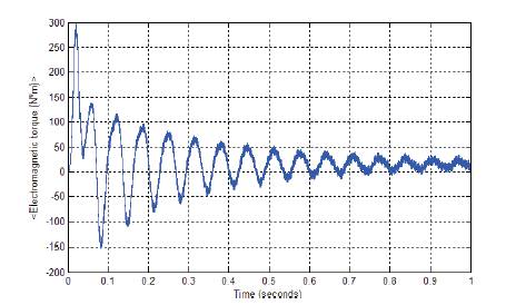
Figure 10. Electromagnetic Torque for f=20 Hz
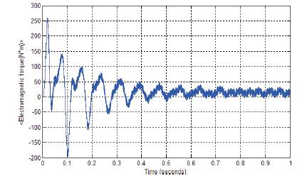
Figure 11. Electromagnetic Torque for f=15 Hz
The closed loop induction motor fed PWM inverter simulink model is as shown in Figure. 12, which is simple open loop DC drive controlling an induction motor. The modern control techniques such as field oriented control or direct torque control technique can also be used with PWM inverter fed motor and can obtain same flexibility in the speed and torque control like DC machines.
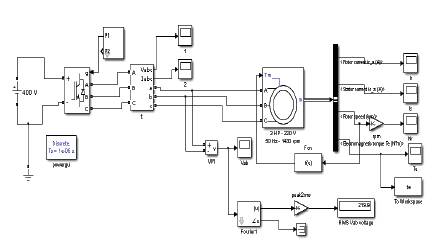
Figure 12. Closed loop Model of induction motor fed PWM inverter
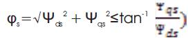
The field control is an attractive control method but it has a serious drawback. It relies heavily on precise knowledge of the motor parameters. The rotor time constant is particularly difficult to measure precisely, and to make matters worse, because it varies with temperature. The torque control method efficiently controls the induction motor. It estimates the stator flux and electric torque in the stationary reference frame and terminal measurements.
The following relation is used for the torque control method:
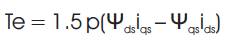
The Electromagnetic Torque is given as follows
The estimated stator flux and electric torque are controlled directly by comparing them with their respective demanded values using the hysteresis comparators. The outputs of the two comparators are used as input signals of an optional switching table. The rotor speed is fed back and directly connected to the torque input. The value of the feedback constant k is calculated as 6.693x10⁻⁴
The simulation results of closed loop model are as shown in Figure.13. The three motor current signatures are compared with obtained results by the open loop model. Those motor signatures are stator current, rotor speed and electromagnetic torque
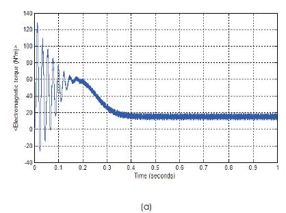
Figure 13. Symmetrical Condition of the Motor, Closed Loop (a) Electromagnetic Torque
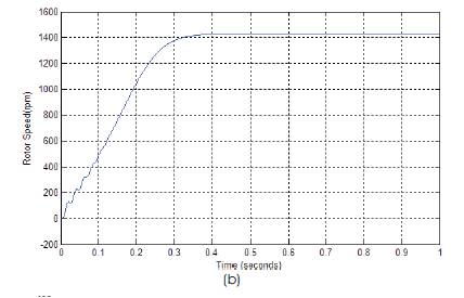
Figure 13. Symmetrical Condition of the Motor, Closed Loop (b) Rotor Speed
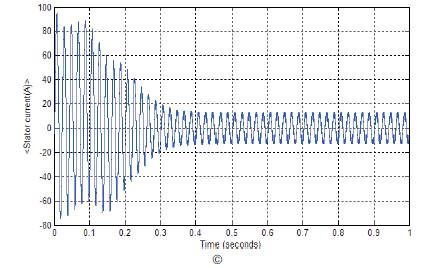
Figure 13. Symmetrical Condition of the Motor, Closed Loop(c) Stator Current
In the open loop model results, they have observed that the motor signatures are reaching in the steady state condition after passing through the transient time i.e. 0.4 sec. In the closed loop model, for the same values, transient time is decreased. Therefore, torque control method can be used efficiently for the control of induction motor.
The harmonic analysis for open and closed loop models has been done for its output stator current and input lineto- line voltage. The waveforms of stator current for 1 KHz and 5 KHz maximum frequencies are as shown in Figure. 14 and Figure. 15 for open loop. It is observed from Figure. 14 and Figure. 15 that when the maximum frequency is increased, then the Total Harmonic Distortion(THD) will also get increased. Therefore, in the model, they have to choose the accurate maximum frequency for achieving the maximum efficiency of the motor

Figure 14. THD in stator current for open loop when max. frequency is 1 Khz
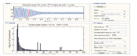
Figure 15. THD in stator current for open loop when max. frequency is 5 KHz
The harmonic analysis for closed loop model has also been done for 1 KHz and 5 KHz frequencies. The waveforms of output stator current for 1 KHz and 5 KHz maximum frequencies are as shown in Figure. 16 and Figure. 17 for closed loop. It has been observed from Figure. 16 and Figure. 17 that when the maximum frequency is getting increased then the total harmonic distortion will also be getting increased. But, in the closed loop, obtained THD in the output stator current is less as compared to open loop.
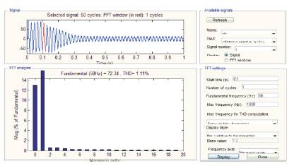
Figure 16. THD in stator current for closed loop when max. Frequency is 1 KHz
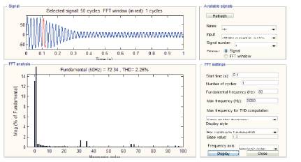
Figure 17. THD in stator current for closed loop when max. Frequency is 5 KHz
The THD in the open loop and closed model for various maximum frequencies is as shown in Table 6. The fundamental frequency is set at 50 Hz for various maximum frequencies. It has clearly been observed from Table 6
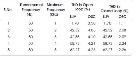
Table 6. THD in Open Loop and Closed Loop Models
The output stator current THD is more in the open loop as compared to closed loop but for the line-to-line voltage, THD is same in both the cases (open/close). It is because they are not controlling input line-to-line voltage. Therefore, PWM inverter output voltage will be unchanged in open loop as well as closed loop. The THD in the line-toline voltage as well as output stator current is very much less for 1 KHz maximum frequency and, it is because of the Fact that IGBT based PWM inverter efficiently control the motor upto 1 KHz frequency inspite of disturbance in the supply. When the maximum frequency further is increased, the THD in the line-to-line voltage is being increased, but the THD in current is less. It has been observed in the previous researches that the THD value was quite high in the voltage as well as current. Therefore, if they use IGBT inverter fed induction motor model, that may get maximum efficiency of the motor in various applications.
Since they used IGBT inverter for induction motor controlling purpose IGBT gives excellent results in various power electronics applications efficiently due to its advantages. Therefore, despite of high switching frequency, there is very less harmonics in the output stator current.
The THD for open loop and closed loop with various maximum frequencies are shown in Table 6.
Therefore, it can be concluded that from the above Table 6 in the MATLAB/Simulink during modeling they have to choose the correct maximum frequency for better results. The THD waveforms for current in the closed loop are as shown in Figure.16 and Figure.17.
The fundamental component and Total Harmonic Distortion (THD) of the Vab voltage are displayed above the spectrum window. The magnitude of the fundamental of the inverter voltage (311 V) is compared well with the theoretical value (311 V for m=0.9) as shown in Figure.18 and Figure.19.
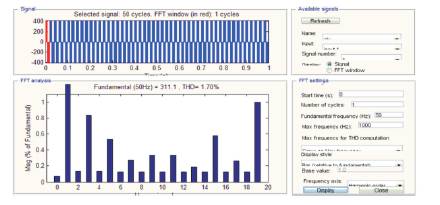
Figure 18. THD in input voltage for open/closed loop when max. Frequency is 1 Khz.
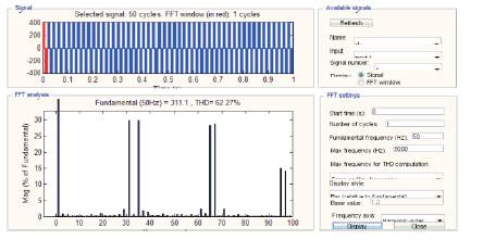
Figure 19. THD in input voltage for open/closed loop when max. Frequency is 5 KHz.
Harmonics are displayed in percent of the fundamental component. As expected, harmonics occur around multiples of carrier frequency (n×33± k). Highest harmonics (30%) appear at 31st harmonic and 35th harmonic (33+2). It can be clearly seen in Figure 19. It is noted that the THD value for voltage (62.27 %) has been computed for the specified 0 to 5000 Hz frequency range
The harmonic distortion waveforms for open/closed loop line-to-line voltage are as shown in Figure. 18 and Figure. 19. From Figure. 18, it has been observed that the THD for line-to-line voltage for 1 KHz maximum frequency is very low because of the IGBT inverter. Since, the harmonic distortions in the open and closed loops are same of there is no feedback with this input line-to-line voltage
In the present paper, an open and closed loop induction motor fed PWM inverter models have been proposed and developed in the recent Matlab/Simulink. From both models, the transient behavior of the motor has been analysed. It has been observed that from the obtained results for open and closed loop models, the closed loop model with torque control method gives better results as compared to open loop with reduced harmonics. The field control method is not only used for controlling the induction motor because of its some serious drawbacks explained earlier. The extensive simulation has been carried out for 3HP, 4 pole, 50 Hz induction motor and obtained simulation results gave ultimate solution for the wide range of speed control with reduced harmonics. It may also be concluded that even with the rapid advancement in power electronics and drives; the constant speed induction motor may be used as variable speed induction drive systems by using static frequency inverter. For the variable speed induction motor, the motor must be fed by static frequency inverter rather than connecting it directly to the sinusoidal power line. Therefore, it can control wide range of speed efficiently by V/f speed control method. The V/f control method has also been implemented for open loop model and observed that it is also able to control a wide range of speed efficiently. The transient behavior of the motor has also been discussed and observed that the maximum transient peak is completely controllable with varying inverter frequency. These models may be used in various applications in the future. From these models different motor faults can be diagnosed, with different Digital Signal Processing (DSP) techniques. The utilization of Squirrel Cage Induction Motors with electronic inverters provide great advantages on account of cost and energy efficiency as compared with other industrial solutions for varying speed applications. Nevertheless, the PWM inverter affects the motor performance and might introduce disturbances into the main power line. Thus, it requires a good understanding of the whole power system as well as the interactions among its parts one another (e.g power line-frequency inverter-induction motor-load).
The simulated models may be used in various applications in Power Electronics and Electric Drive Applications.