Figure 1(a) Basic Arrangement of D-TATCOM
The D-STATCOM is a shunt connected FACTS device which supplies reactive power to the load to improve the voltage stability of the load buses. The D-STAT COM in multi bus system is capable of reducing the losses and improving the voltage regulation. This work deals with the comparison of Push Pull and Voltage Inverter based D-STATCOM for multi bus system. Eight bus system is modeled using the elements of SIMULINK. The models are developed for eight bus systems with and without D-STATCOM. The two D-STATCOM systems are compared with respect to total harmonic distortion and reactive power comparison. The D-STATCOM is studied with respect of the voltage stability improvement at the load buses. The results of VSI based D-STATCOM system are compared with those of Push pull inverter based D-STATCOM system.
The electrical power utilities improve efficiency in the operation of the power system networks by reregulating the industries and opening it to their private competitors. Developing the new approaches to Power System Operation and Control are required for overload relief, and efficient and reliable operation. Supporting dynamic disturbances such as transmission lines switching, loss of generation, short-circuits and load rejection, needs the reactive control to be fast enough to maintain the desired voltage levels and the system stability [1].Flexible AC Transmission Systems (FACTS), besides the underlying concept of independence,
Control of active and reactive power flows are an efficient solution to the reactive power control problem and voltage in transmission and distribution systems, offering an attractive alternative for achieving such objectives. Originally, equipment based on thyristors, like TCR (Thyristor Controlled Reactor), TSC (Thyristor Switched Capacitor), and SVC (Static Var Compensator), have been employed in solving these problems, but now equipment based on controlled switches such as GTO, IGBT and IGCT is common. The Static Synchronous Compensator (StatCom), and Static VAR Compensator (SVC) are the two types of shunt controllers for injection of reactive current, and their primary function is the dynamic voltage control. Related to the SVC, the current is a function of the square of the line voltage and hence its reactive power is function of square of the line voltage. Thus, the dynamic voltage is say 80%, the injected reactive power is reduced to 64%, and just more of them is needed. For similar performance, Stat Com size would be much smaller and should be the more cost effective of both. The StatCom is one of the most used FACTS devices [2]for many applications. In relation to the SVC, the StatCom differs that it can synthesize the reactive power from small values of storing elements, when operating in the linear region and, it exhibits a similar behavior to the SVC. However, it is seen by the system as a source of synchronous voltage, while the SVC is seen as a variable admittance[3][4]. From the reactive power point of view, the StatCom provides the operating characteristics similar to a rotating synchronous compensator without the mechanical inertia, and it provides rapid controllability on the three-phase voltages both in magnitude and phase angle. It has received great attention due to its diverse possibilities of construction and operation. The improvements and benefits that can be gained when using a StatCom include the following:
This paper analyzes the key issues in the power quality problems. As one of the prominent power quality problems, the origin, consequences and mitigation techniques of voltage sag problem has been discussed in detail. The STATCOM is applied to regulate the transmission voltage to allow greater power flow in a voltage limited transmission network, in the same manner as a Static Var Compensator (SVC). The STATCOM has further potential by giving an inherently faster response and greater output to a system with depressed voltage and offers the improved quality of supply. The FACTS controllers are used to regulate the system voltage. The main applications of the STATCOM are Distribution STATCOM (D-STATCOM) which exhibits the high speed control of reactive power to provide the voltage stabilization and the other type of system control. The DSTATCOM protects the utility transmission or distribution system from voltage sag and /or flicker caused by rapidly varying reactive current demand. During the transient conditions the D-STATCOM provides leading or lagging reactive power to active system stability, power factor correction and load balancing and /or harmonic compensation of a particular load [6,7],
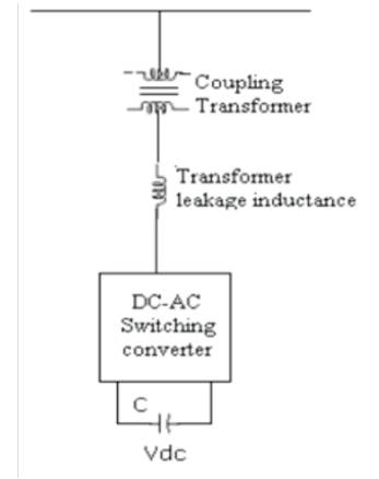
The power electronic based three phase reactive power compensation equipment is the D-STATCOM, which generates and /or absorbs the reactive power whose output can be varied so as to maintain control of specific parameters of the electric power system. The D-STATCOM basically consists of a coupling transformer with a leakage reactance, a three phase GTO/IGBT Voltage Source Inverter (VSI), and a DC capacitor .The Basic Arrangement of D-STATCOM is as shown in Figure1a. The AC voltage difference across the leakage reactance power exchange between the D-STATCOM and the Power system, such that the AC voltages at the bus bar can be regulated to improve the voltage profile of the power system, which is primary duty of the D-STATCOM. However a secondary damping function can be added in to the DSTATCOM for enhancing power system oscillation stability. The D-STATCOM provides operating characteristics similar to a rotating Synchronous compensator without the mechanical inertia. The D-STATCOM employs solid state power switching devices and provides rapid controllability of the three phase voltages, both in magnitude and phase angle. The D-STATCOM employs an inverter to convert the DC link voltage Vdc on the capacitor to a voltage source of adjustable magnitude and phase. Therefore the D-STATCOM can be treated as a voltage controlled source. The D-STATCOM can also be seen as a current controlled source.
Figure 1(a) Basic Arrangement of D-TATCOM
The objective of a VSI is to produce a sinusoidal AC voltage with minimum harmonic distortion from a DC voltage. The operation of the D-STATCOM is as follows, the voltage is compared with the AC bus voltage system (Vs). When the AC bus voltage magnitude is above that of the VSI magnitude (Vc); the AC system sees the D-STATCOM as inductance connected to its terminals. Otherwise if the VSI voltage magnitude is above that of the AC bus voltage magnitude, the AC system sees the D-STATCOM as capacitance to its terminals. If the voltage magnitudes are equal, the reactive power exchange is zero. If the D-STATCOM has a DC source or energy storage device on its DC side, it can supply real power to the power system. This can be achieved by adjusting the phase angle of the DSTATCOM terminals and the phase angle of the AC power system. When the phase angle of the AC power system leads the VSI phase angle, the DSTATCOM absorbs the real power from the AC system, if the phase angle of the AC power system lags the VSI phase angle, the DSTATCOM supplies real power to AC system (5).
The main function is to regulate the key bus voltage magnitude by dynamically absorbing or generating reactive power to the ac grid network, like a thyristor static compensator. This reactive power transfer is done through the leakage reactance of the coupling transformer by using a secondary transformer voltage in phase with the primary voltage (network side). The V-I characteristics of the statcom is as shown in Figure.1(b).
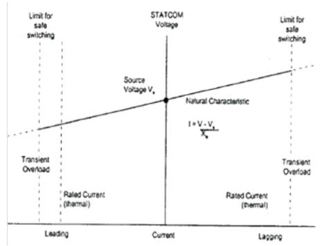
Figure 1(b) Natural V-I characteristic of a D-STATCOM
The real and reactive powers in D-STATCOM are given by the following equations.
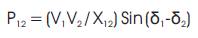
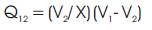
The basic principle is to use a voltage source inverter that generates a controllable AC voltage source behind a leakage reactance. The voltage difference across the transformer reactance produces the active and reactive power flows with the network. The exchange of reactive power with the network is obtained by controlling the magnitude V and the exchange of active power results from a control of the phase shift w. The exchange of active power is only used to control the DC voltage [8]. Under the steady state conditions and ignoring the losses the exchange of active power is done and thus the DC current are zero. A complete STATCOM generally combines several converters. Alternative inverter structures are being designed, for example using singlephase bridges in series. The most common methods used for controlling the AC voltage generated by the inverter are, DC variable voltage with a full wave inverter, sometimes called Pulse Amplitude Modulation (PAM). Constant DC voltage with a Pulse-Width Modulated inverter (PWM).
The Voltage Source Inverter (VSI) is the building block of a D-STATCOM and other FACTS devices. A very simple inverter produces a square voltage waveform as it switches the direct voltage source on and off. The basic objective of a VSI is to produce a sinusoidal AC voltage with minimal harmonic distortion from a DC voltage. Figure 2 shows the STATCOM generates a balanced 3- phase voltage whose magnitude and phase can be adjusted rapidly by using semiconductor switches. The STATCOM is composed of a voltage-source inverter with a DC capacitor, coupling transformer, and signal generation and control circuit. The voltage source inverter for the transmission STATCOM operates in multi-bridge mode to reduce the harmonic level of the output current [9]. Figure 2(b) shows a single-phase equivalent circuit in which the STATCOM is controlled by changing the phase angle between the inverter output voltage and the bus voltage at the common point connection point. The inverter voltage Vi is assumed to be in phase with the AC terminal voltage Vt [10].
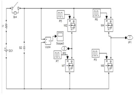
Figure 2 (a) VSI based D-STATCOM
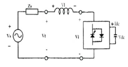
Figure 2. (b) Detailed operating principle
The STATCOM supplies reactive powers to the AC system if the magnitude of Vi is greater than that of Vt. It draws reactive power from the AC system if the magnitude of Vt is greater than that if Vi.
The push-pull inverter circuit comprising a transformer with a power output end coupled to a load and two power input ends is as shown in Figure 3. A power driver unit is connected between the two power output ends. A power supply unit, and the power driver unit receives a power signal and outputs in two sets of drive signals having same frequency. Circuit diagram of Push-Pull inverter is shown in Figure 3.This circuit is also called parallel inverter since the capacitor appears in parallel with the transformer.T1 and T2 conducts alternatively to produce the AC output.
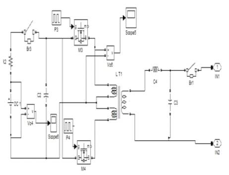
Figure 3. PUSH PULL based D-STATCOM
For simulation studies, the eight bus system is considered. The circuit model of eight bus system is shown in Figure 4a. Each line is represented by series impedance model. The shunt capacitance of the line is neglected. By closing the breaker in series with the load an additional load is added in parallel with load- 1. Scopes are connected to display the voltages across the two loads. At t = 0.2sec, additional load is connected voltage across the load-1 decreases. This fall in voltage is due to the increased voltage drop. The voltage across bus 4 is as shown in Figure 4(b). The active and reactive power across bus(4) are as shown in Figure 4( c ).
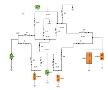
Figure 4(a). Eight Bus System
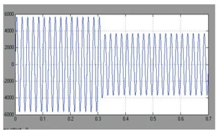
Figure 4(b) Voltage across bus-4
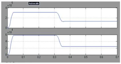
Figure 4(c) Real and Reactive Power across Bus -4
The VSI based D-STATCOM added with an eight bus system is as shown in Figure 5(a). The D-STATCOM is connected in the line between buses 4 and 8. The D- STATCOM Model is shown in Figure 5(b). The active and reactive power in the load-1, voltages across bus-4 is as shown in Figure 5(c). It can be seen when the voltage across load-1 decreases and resumes to the rated value due to the injection of voltage by the D-STATCOM. The RMS voltage across bus-4 is as shown in Figure.5(d). The real and reactive powers across bus-4 are as shown in Figure.5(e). Bus number Vs Reactive power(Q) is as shown in Figure.5(f). The FFT analysis for voltage is as shown in Figure.5(g).
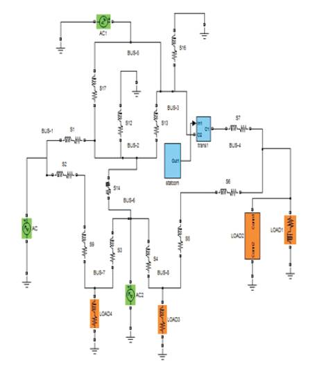
Figure 5(a) Eight Bus System with VSI based D-STSTCOM
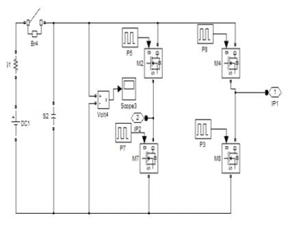
Figure 5(b). VSI based DSTATCOM
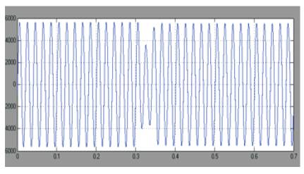
Figure 5(c).Voltage across bus-4
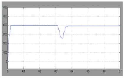
Figure 5(d) RMS Voltage
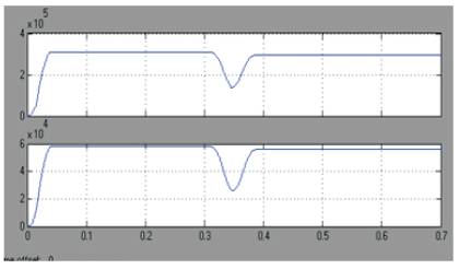
Figure 5(e). Real and Reactive Power across bus-4
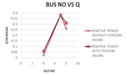
Figure 5(f). Bus number Vs Reactive Power (Q)
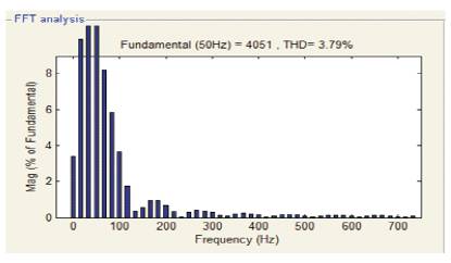
Figure 5(g). FFT analysis for voltage
The Push Pull Inverter based D-STATCOM added with an eight bus system is shown in Figure.6(a). The D-STATCOM is connected in the line between buses 4 and 8. The PUSH PULL based D- STATCOM Model is shown in Figure.6(b). The active and reactive power in the load-1, voltages across D- STATCOM are shown in Figure.6(c). It can be seen that the voltage across load-1 decreases and resumes to the rated value due to the injection of voltage by the DSTATCOM. The RMS voltage across bus-4 is as shown in Figure.6(d). The real and reactive power across bus-4 is shown in Figure.6(e). Bus number Vs Reactive Power Q) is shown in Figure.6(f). FFT analysis for voltage is as shown in Figure.6(g).
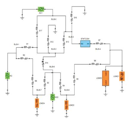
Figure 6(a). Eight Bus System with PUSH PULL based D-STSTCOM
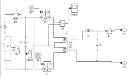
Figure 6(b). PUSH PULL based D-STATCOM
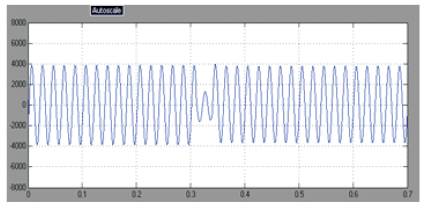
Figure 6(c). Voltage across bus-4
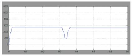
Figure 6(d). RMS Voltage
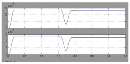
Figure 6(e). Real and Reactive Power across bus-4
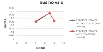
Figure 6(f). Bus number Vs Reactive Power
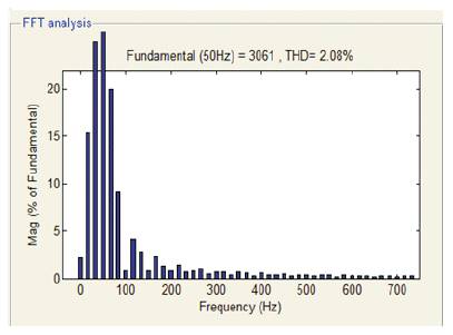
Figure 6(g) FFT Analysis for Voltager
Thus the D-STATCOM is able to mitigate the voltage sag produced by the additional load. Power quality is improved since the voltage reaches at the normal value. Summary of real and reactive powers with and without VSI based D-STATCOM are given in Table1. The reactive power increases by the addition of D-STATCOM and this is due to the increase in the bus voltage. Summary of real and reactive powers with and without PUSH PULL based DSTATCOM is given in Table 2. The reactive power increases when the D-STATCOM is added. Comparison of VSI and PUSH PULL based D-STSTCOM systems is given in Table 3.
THD in Push Pull inverter system is less by 1.7% than VSI based D-STATCOM system is given in Table 3.
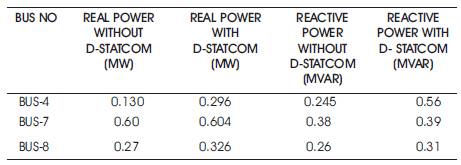
Table 1. Summary of Real and Reactive powers with and without VSI based D-STATCOM
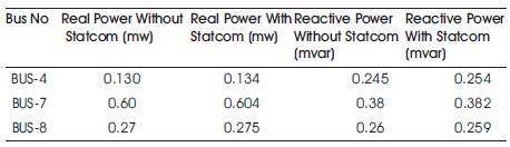
Table 2. Summary of Real and Reactive powers with and without Push Pull based D- STATCOM
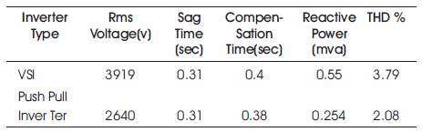
Table 3. Comparison between VSI and Push Pull Inverter based D_STSTCOM
Eight bus system is modeled and simulated using MATLAB SIMULINK. The simulation results of eight bus system with and without VSI based D-STATCOM are presented, and also the, simulation of eight bus system with and without Push Pull inverter based D-STATCOM is done. VSI and Push Pull inverter based D-STATCOM systems are compared. Voltage stability is improved by using both types of DSTATCOM. This system has improved with reliability and power quality. Push Pull inverter system is found to be superior to the VSI based system. The simulation results are in line with predictions. The scope of the present work is the modeling and simulation of eight bus system and compared. This concept can be extended to 64 bus system.