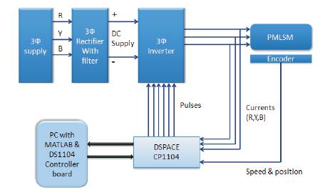
Figure 1. Block diagram of real time implementation using dSPACE
This paper proposes speed control of permanent magnet linear synchronous motor using Space Vector Pulse Width Modulation (SVPWM). Among the various modulation strategies Space Vector Modulation Technique is the efficient one because of its better spectral performance, better dc bus utilization and easier digital realization. With SVPWM the performance of PMLSM is improved because it eliminates all the lower order harmonics in the output voltage of the inverter when compared to the conventional SPWM technique. The open loop & closed loop simulation model for SVPWM with PMLSM is constructed using MATLAB/SIMULINK. Hardware is implemented and validated Using dSPACE ds1104 controller board.
Permanent Magnet Linear Synchronous Motor (PMLSM) is a kind of driving equipment for converting electrical energy into linear movement directly. The linear drive offers high efficiency, high reliability, high performance motion control and low vibration and noise [1]. PMLSMs are increasingly used as actuators in many automation control fields, including computer controlled machining tools, robots, semiconductor manufacturing equipment, transport propulsion and levitation [2].
Due to the improvement of fast-switching power semiconductor devices and the machine control algorithm, more precise Pulse Width Modulation (PWM) method finds particularly the growing interest. For the ac machine drive application, full utilization of the dc bus voltage is extremely important in order to achieve the maximum output torque under the all operating conditions. In this aspect it is compared with any other PWM methods for the voltage source inverter, the PWM method based on the voltage space vectors are excellent in dc bus utilization [3]. Moreover when compared to the sine triangle PWM method, the current ripple of steady state operation can be minimized in this method.
SVPWM inverter is viewed as a voltage space phasor generator but not as a three phase voltage in SPWM and the hysteresis control system. The SVPWM inverter controls not only the magnitude and angular velocity but also the angular position of the voltage phasor [4]. The position variable has a major impact on the dynamics of the motor drive. This invention singly and uniquely had the most powerful effects in obtaining the highest steady state and dynamic performance of the ac machines. The advantage of SVPWM is lower harmonics, switching losses and 15% higher utilization ratio of voltage [5]. The placement of zero voltage intervals in between the voltage pulses decrease the current ripples.
The dSPACE-1104 controller board is an interface between the host computer, the driving circuit, A/D and D/A converters, serial interfaces and sensors [6]. One of the best features of dSPACE is the earlier of building realtime implementation as shown in Figure1. dSPACE has a software interface to the controller board based on the MATLAB Simulink. Once the Simulink model is completed, dSPACE software can convert it into real-time DSP code. Then, it downloads the code to the controller board, and executes the program in real time. dSPACE software also has the tools to display, store data, and change the parameters online.
Figure 1. Block diagram of real time implementation using dSPACE
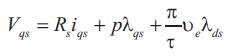
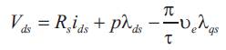
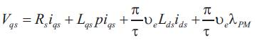
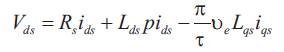
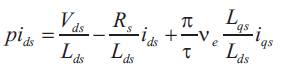
The voltage equations for the permanent magnet Linear synchronous motor in synchronously rotating reference frame are [7],
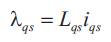
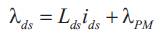
Where λds, λqs = d & q-axis stator magnetic fluxes By substituting equation numbers (3) & (4) in equations (1) & (2) respectively, we get,
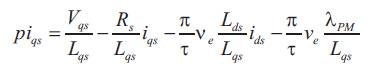
By rearranging equations (5) & (6), then
The electromagnetic thrust is given by,
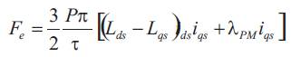
where, λPM = Permanent magnet flux
P = Number of pole pair
Mechanical thrust equation is,
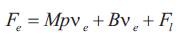
Where, Fe = Electrical thrust
F1 = Load thrust
M = Mass of the mover
B = Damping coefficient
The proposed control diagram of PMLSM is as shown in Figure 2. The P.I.D. controller operates on the speed error and the outputs as a thrust command. The reference current generator produces reference current Iq* corresponding to thrust command. The Reference current is compared with the actual current and fed into the current controller. The output of the current controller is Vq & Vd which is input to the SVPWM inverter. Voltage source d SVPWM inverter drives the PMLSM.
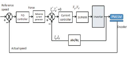
Figure 2. Block diagram of the proposed system
The output of the P.I.D. controller has a torque signal as shown in Figure 3. Its mathematical expression in the time domain is given as follows [8].
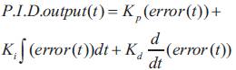
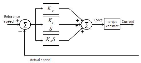
Figure 3. Block diagram of PID controller
This section is devoted to the development of Space vector PWM for a two-level voltage source inverter. There are six switching devices and only three of them are independent as the operation and two power switches of them are same leg are complimentary. The combination of these three switching states gives out the eight possible space voltage vectors. The space vectors form a hexagon with 6 distinct sectors, each spanning 60 degrees in space. At any instant of time, the inverter can produce only one space vector. In space vector PWM a set of three vectors (two active and one zero) can be selected to synthesize the desired voltage in each switching period.
Out of eight topologies six (states 1-6) produce a non-zero output voltage and are known as active voltage vectors and the remaining two topologies (states 0 and 7) produce zero output voltage (when the motor is shorted through the upper or lower transistors) and are known as zero voltage vectors. Various possible switching states are shown in Figure 5. Space vector is defined as,
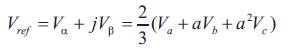
where,
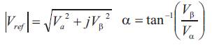
The eight vectors including the zero voltage vectors can be expressed geometrically as shown in Figure 6. Each of the space vectors, in the diagram represents the six voltage steps developed by the inverter with the zero voltages V0 (0 0 0) and V7 (1 1 1) located at the origin. Space Vector PWM requires the averaging of the adjacent vectors in each sector. Two adjacent vectors and zero vectors are used for synthesis the reference input determined from Figure 4 for sector I. Using the appropriate PWM signals a vector is produced that transitions smoothly between sectors and thus provide a sinusoidal line to line voltages to the motor. In order to generate the PWM signals that produces the rotating vector, Vref can be found with two active and one zero vector.
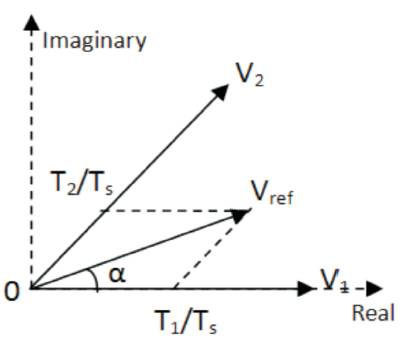
Figure 4. Phasor Diagram for sector-1
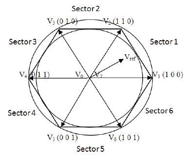
Figure 5. Space Vector representation of Phase Voltage
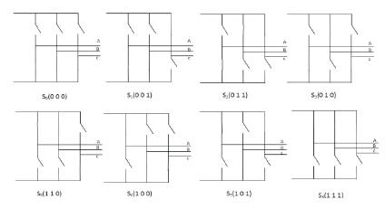
Figure 6. The switches position during eight topologies
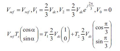
For sector 1 i.e 0 to  Vref can be located with V0 , V1 and V2, Vref in terms of the duration time can be considered as follows,
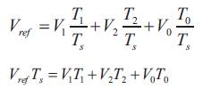
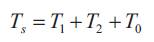
The total cycle is given by,
The position of Vref, V1, V2 and V0 can be described with its magnitude and angle. The Voltages at each switching vector is tabulated in Table 1.
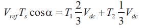
Dividing these in real and imaginary parts simplifies the calculation for each duration time.
Real part:
Imaginary part:
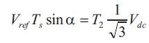
T1 and T2 is given by,
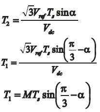
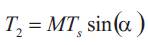
where,

where, M=modulation index
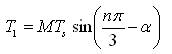
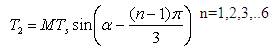
Generalizing the time expressions for n sectors,
The periods T1, T2 depends only on the reference vector amplitude Vref and the angle α.
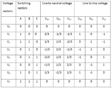
Table 1. Voltages at each Switching Vector
The d & q-axis voltages from the controller gives the magnitude of the voltage phasor and angle. From this information the time duration of switching vectors & zero vectors are calculated. The sampling period is an additional input to SVPWM to endow a desired varying switching frequency that is useful in optimizing the efficiency of the motor drive over the entire speed torque region.
MATLAB Simulink is used to design the control loop as shown in Figure 7. Several functional blocks in the Simulink model calculates the reference voltage command and generate switching logic signals. Figure 8 shows the simulation results for speed, Motor thrust and Motor position.
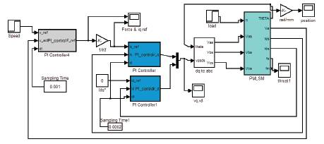
Figure 7. Simulation of Closed Loop Speed control of PMLSM with PID controller
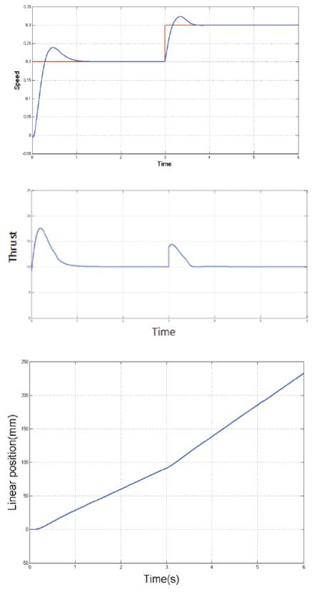
Figure 8. Simulation results of (a) speed (b) Motor thrust (c) Motor position for step change in speed from 0.2 m/sec to 0.3 m/sec at load torque 10 N
The dSPACE RTI library converts the control logic and algorithm of the Simulink model into C code and downloads the code into dSPACE controller's memory. Then the dSPACE controller board can run the code in real time and archives the functions designed in Simulink. Simulink model of PMLSM control with dSPACE SVPWM block is shown in Figure 9 and inputs to the SVPWM is shown in Figure 11. Current sensor interfacing is shown in Figure 12. The complete Experimental setup is as shown in Figure 10. Hardware output results of motor three phase current, speed and position is shown in Figures 13,14 & 15 respectively.
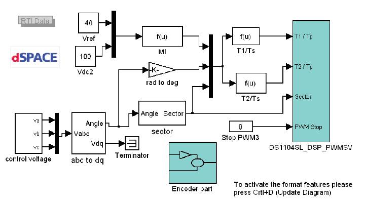
Figure 9. Real time Simulink model of SVPWM with dSPACE
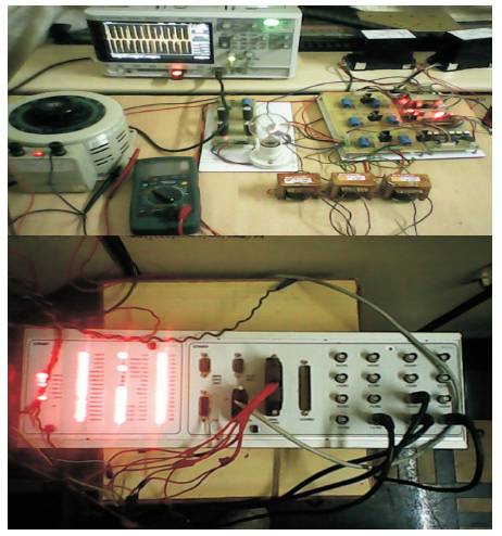
Figure 10. Experimental setup of PMLSM
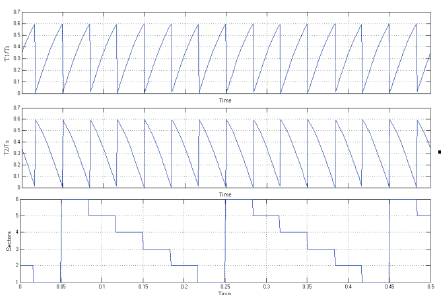
Figure 11. Inputs for dspace block(T1/Tp,T2/Tp,sectors)
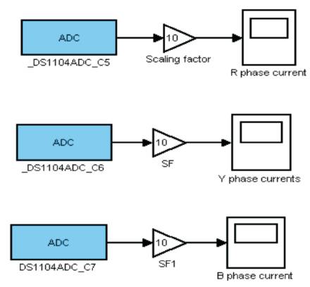
Figure 12. Scoping of Real-Time Currents
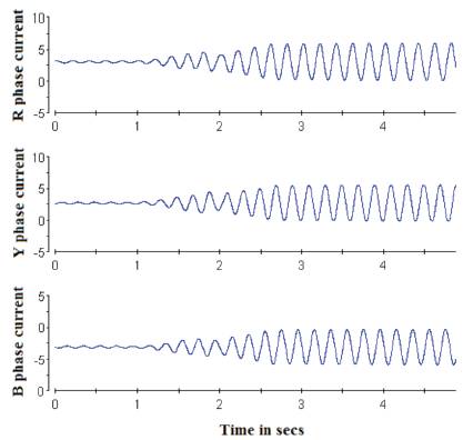
Figure 13. 3phase motor currents at motor speed 0.2m/sec
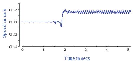
Figure 14. PMLSM speed for a step change in speed from 0 to 0.2meter/sec at 2 sec
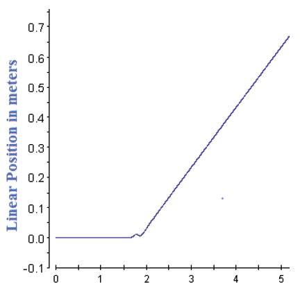
Figure 15. PMLS motor position in meters
Speed control of PMLSM with Space Vector Pulse Width Modulation is implemented using dSPACE DS1104 real time control board. The controller is implemented by writing c-programs and all the control commands are given from the Control Desk software using a real time environment. With the sensors used by the control system, real time measurements are taken with the Control desk software and the data from the experiments are saved and compared with simulations. It has observed that the real time output is almost similar to the simulation results.