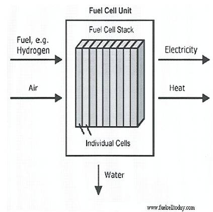
Figure 1. Basic overview of the operation of a Fuel Cell unit[11].
Fuel Cells offer a realistic, sustainable and clean alternative energy option for stationary and mobile applications. Hydrogen and fuel cell technologies are recognised by many as possible long term energy solutions, but to-date have failed to make an impact on the energy market. This is due to a number of key reasons, some of which include, efficiency, scale, accessories and power output. Applying fuel cells to small telecommunication components requires the applications of Micro and Nanotechnology, which have yet to be perfected to make them long lasting and cost effective.
This paper outlines the reasons for commercialisation of fuel cells and supports the argument that utilising hydrogen technology should be done in an environmentally friendly manner from the offset to prevent further damage to the environment. In particular, the paper focuses on the research, design and development of a Single Alkaline Fuel Cell Test Bed and outlines the AFC's capabilities and limitations for satisfying such energy needs.
With fossil fuel reserves dwindling, volatility and unrest in the Middle East, and environmental damage world economies have refocused their attentions in finding an alternative renewable fuel source. The emergence of new industrial economies in China and India has led to increased demand for fossil fuel, resulting in massive price increases. For the last fifty years research into renewable energy sources has lacked sufficient investment. But now it seems the emphasis has shifted and funding is being made available in a proactive manner by various governments eager to encourage the commercialisation of renewable energy technology and reduce carbon taxes [1].
The fuel cell has been in existence for over a hundred years and still there are numerous problems to be resolved before commercialisation and mass production can be realised.
William R. Groves (1811- 1896) a barrister in Swansea discovered the principle of the fuel cell while conducting electrolysis experiments in 1842. Groves generated electricity by reverse electrolysis, from a four cell gas chain and used the generated current to split water into hydrogen and oxygen in an upper cell [2]. Some hundred years later Francis Bacon (1904-1992) took fuel cells from the research stage and produced an Alkaline Fuel Cell (AFC) that became part of the NASA space program and provided the main power source for the Apollo space missions, clocking up thousands of service hours [3]-[5]. The main attraction of the Alkaline Fuel Cell to the space program was its high thermal efficiency (approaching 70%), the use of non noble metals as part of its construction, making it considerably cheaper than its rivals and low hydrogen and oxygen consumption with the only by-products being heat and water, the latter being used for drinking purposes reducing onboard weight [5]. The benefits of the Alkaline Fuel Cell realised by NASA are low temperature, high efficiency, low consumption and cheaper construction. These are the important factors for promoting commercialisation of alkaline fuel cells in today's cost effective market.
Figure 1. outlines the basic dynamics of a fuel cell.
“A Fuel Cell is an electrochemical device that continually converts chemical energy into electric energy (and some heat) for as long as fuel and oxidant are supplied” [4].
The Fuel Cell achieves this conversion via electrochemical reactions that occur at the electrodes when they are connected as part of an external circuit. Conventional batteries have a tendency to consume materials that form an integral part of, or are stored within its structure. A fuel cell does not. Thus a fuel cell follows the principle of the conservation of energy and converts chemical energy into electrical energy and since ideally no part of it should undergo any reversible chemical change, it can continue to operate as long as it is supplied with a suitable fuel (hydrogen) and oxidant (oxygen) and the reaction products (water and heat) are removed.
Pure oxygen (O2) or air is used as the oxidant and the most commonly used fuel is pure hydrogen (H2). Other hydrogen rich fuels such as gasoline, methanol, ethanol, methane and natural gas can be reformed, to produce hydrogen gas to utilise in the fuel cell. If the cell uses pure hydrogen the process results in zero emissions, but the reforming process does emit harmful pollutants into the atmosphere[6].
Figure 1. Basic overview of the operation of a Fuel Cell unit[11].
As part of the alkaline fuel cell system the reactants are fed from outside the cell to the electrodes only when electric power generation is required. The electrodes are coated with a catalyst, usually platinum for H2 and silver for O2 to increase the rate of the reaction. The hydrogen is oxidised at the anode by transferring electrons to the anode and the oxygen is reduced at the cathode by accepting electrons from the cathode. The current generated by the flow of electrons from the anode to the cathode (Galvanic cell) can be used to service external loads, e.g. motors, lights, etc., and the d. c. voltage can be inverted to suit a. c. applications. When the reactants are exhausted the external cylinders are recharged to resume operations. [5]
The nominal voltage of a single cell is approximately 1.05 to 1.23 volts unloaded dropping to 0.7 to 0.9 volts when a load is applied depending on the cell type and design. Therefore in order for fuel cells to be used in a practical application a number of individual cells are joined together to form a fuel cell stack. A single fuel cell has a high current and low voltage output, so cells are joined together in series or parallel to suit required applications and the stacks are designed to locate in any area. Based on the nominal voltage when loaded (0.7~0.9 volts) the number of cells in the stack determines the total voltage and the cell surface area determines the current. The products of current and voltage will give the total power generated.
Advancements in engineering and materials used in the construction of fuel cells have increased their power density to such a level that a stack the size of a small suitcase can be used to power a car[7].
Electrolysis of water is an electrical process where current is passed through an electrolyte causing water to break up into its hydrogen and oxygen constituent elements. It is essentially the fuel cell in reverse and a very useful method of producing pure hydrogen for local or commercial use.
Hydrogen gas is produced at the cathode (negative electrode) and the chemical equation for the reduction of water at this electrode is;
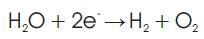
Oxygen gas is produced at the anode (positive electrode) and the donation of electrons due to oxidation at the electrode is expressed as;
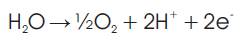
To avoid cross contamination during electrolysis the cell is usually divided allowing the gas bubbles formed at the electrodes due to the decomposing of the water to rise and gather in their respective container[8].
Alkaline Fuel Cells are a highly efficient, low temperature o (50~100oC) potentially low cost cell that have been ignored primarily because of their use of a corrosive electrolyte (Potassium Hydroxide) and inability to use air as an oxidant, (presence of 0.03% CO2) [3]. However research to date has identified that these problems can be rectified. Some advantages of using an AFC are; the use of inexpensive catalysts and membranes, the fact that they can deliver the highest voltage at comparable current densities of all the cells on offer, and are not damaged by carbon monoxide (CO) contamination so the purity of the hydrogen used is not a critical factor to efficient operation.
Dublin Institute of Technology is currently conducting research into Fuel Cell Engineering in collaboration with the Fachshule in Darmstadt and Gaskatel, an industrial partner, both located in Germany. Gaskatel was founded in 1997 by Professor Dr. August Winsel, physicist and his students Dr. Hartmud Joachim Kohnke and Joachim Helmke and specializes in the field of electrochemistry with a current staff of eleven. Originally a research team based in the University of Kassel they were one of a number of universities and companies involved in developing the Eloflux system with Varta AG. This system was considered unique in that the electrolyte was pressed perpendicular to the electrodes through the whole stack and to the gas flow. Therefore, the electrodes and the diaphragms contained an interconnecting system of narrow pores in which the electrolyte was dispersed. Figure 2 shows a simple structure of a fuel cell electrode. The bigger pores were filed with pressurised hydrogen and oxygen, which flowed independently of the electrolyte.
Due to the different pore sizes the gases could not enter the narrow pores and this was critical as any gas cross leakage caused a malfunction of the cell. After Varta AG discontinued their research activities Gaskatel were able to take over their machines, materials, patent and test results and continue researching and developing alkaline fuel cells based on the Eloflux flow system.
The full range of the company's activities include alkaline fuel cells and electrolysers, gas diffusion electrodes, hydrogen reference electrodes, oxygen storage cells, acid concentration sensors and other research and development services in the field of electrochemistry.
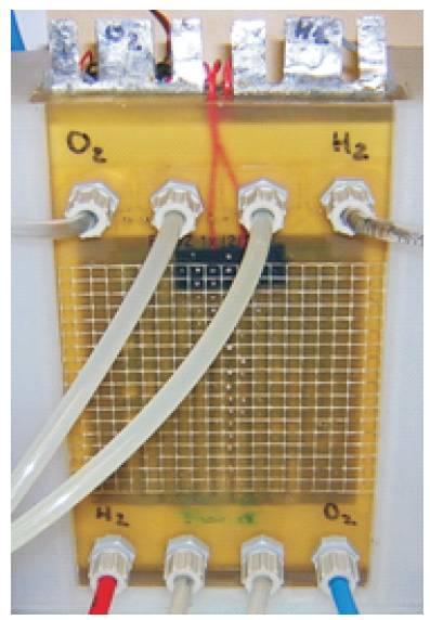
Figure 2. Single Fuel Cell.
The characteristics of the Alkaline Fuel cell are as follows: Dimensions of cell, 110 x 220 x 25mm; Open circuit potential ~ 1.05 V; Loaded 0.7 V ~ 20 A, delivering 14 W,
The current density at different temperatures are 150 mA/cm2 (50oC, 0.7 V), 85 mA/cm2 (23oC, 0.7 V). The cell operates at 250 mA at high temperature and 150 mA at low temperature. It has an active surface area of 100cm and an electrode size of 170 x 100mm. With an active surface area of 100 cm2 and delivering 20 A at 0.7 V and 50 C this corresponds to 0.2 A/cm2. The operating pressures are: Hydrogen 0.5 bar, Oxygen 0.5bar. The cell uses KOH at 50oC or alternatively Sodium Hydroxide (NaOH) operating at a temperature of 70oC.
The cell is a single unit with two hydrogen electrodes and two oxygen electrodes. The supply for the gases and electrolyte are situated at the bottom of the cell. This allows the cell to benefit from the fact that hydrogen is light and will rise through the cell as opposed to being pushed, and oxygen will also flow freely through the cell as will any trapped bubbles or inert gases. Figure 3 shows the various gas (H2/O2) and electrolyte connections. The cell has one active separator and two passive separators. It has two electrolyte distributors (KOH1 and KOH2), and it is possible as part of the KOH supply to the cell to connect them in series or parallel. Two heating elements are also fitted between the positive and negative poles to speed up cell heating. The wiring for the two heating foils can be connected in either series (24 VDC, 1A) or parallel (12VDC, 2A).
Initial heating of the cell with the foils will raise cell temperature but as soon as the electrolyte commences circulation the temperature of the cell reduces drastically and cannot be kept constant unless the circulating electrolyte is also heated. As part of the testing procedure a return beaker positioned on a hot plate was used instead of a reservoir. Heating the cell must be done in conjunction with some form of temperature control. The temperature of the cell must be limited to 55oC. To monitor the temperature a Pt. 100 resistor is also positioned inside the cell in close proximity to each heating element to allow for the temperature of the cell to be monitored to prevent overheating the cell. To prevent gas or electrolyte cross over the cell must be operated at a gas pressure of approximately 0.5 bar. If crossover occurs the cell becomes inactive.
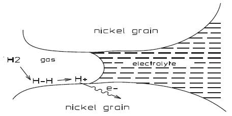
Figure 3. Operation of electrode.
The inner construction of the Gaskatel fuel cell is shown in Figure 4.
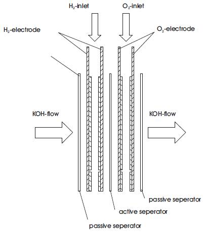
Figure 4. The inner construction.
Working from left to right is the first passive separator followed by a pair of hydrogen (H2) electrodes, the active separator, a pair of oxygen (O2) electrodes and the second passive separator. The electrolyte is mobile and the flow is horizontal from left to right through all the components. The gas flow is vertical and only through the electrodes.
1.2.2 The SeparatorThe separator is made from a porous plastic film, if the electrolyte wets the separator then the potassium hydroxide electrolyte (KOH) can pass through it but the gas cannot up to a pressure of 1 bar approx, (this limit is called the bubble point). If this pressure (bubble point) is exceeded then the gas will push the electrolyte out of the pores. The passive separators only separate the KOH and gas chambers from each other but the function of the active separator is to separate the hydrogen from the oxygen, insulating the electrodes from each other to prevent a short circuit. When the ions are migrating from one electrode to the other they must pass through the active separator.
1.2.3 The ElectrodesThe hydrogen electrode at the anode is made of Raney nickel and polytetrafluoroethylene (PTFE) a stable wet proofing agent and the oxygen electrode at the cathode is made of silver and PTFE. Bacon used nickel in his initial alkaline cell because it has a high catalytic activity for hydrogen oxidation and Raney metals are a good solution to achieving the activity and porosity needed in an electrode [5].
Raney metals are formed through mixing an active metal with an inactive metal like aluminium. The inactive material (aluminium) is then removed from the mixture by dissolving it in a strong alkali. What remains is a completely active porous nickel material with a very high surface area. The pore sizes and distribution depend on the ratio of nickel to aluminium (usually 1:1) and the particle size. The Gaskatel electrodes consist of a nickel net with a film of carbon pressed onto it. The nickel net gives good electrical conductivity and mechanical stability.
The carbon net has hydrophilic pores where the KOH can pass and hydrophobic pores where gas can pass. The gas enters the electrode at the gas port and moves along the gas header (see Figure 5) from where it distributes over the whole electrode.
1.2.4 ElectrolyteThe optimum electrolyte for a fuel cell depends on a number of factors which include material costs, fuel, oxidant, operating temperature, corrosion properties of cell material, electrolyte stability and conductivity as a function of operating conditions and electrode performance as a function of reactants and electrolyte. In alkaline systems, the preferred electrolyte is usually the aqueous potassium hydroxide (KOH), which has a higher conductivity than most other alternatives (sodium hydroxide); it is also worth noting that the conductivity of concentrated KOH rises rapidly with temperature [5].
Vehicles must perform effectively and reliably in different environments so it is important that any fluids utilised in a transport situation must have a high boiling point and a low freezing point, it must also maintain a stable viscosity regardless of the temperatures or conditions it encounters. Figure 6 shows the effect that the concentration, percentage of potassium hydroxide to water has on the boiling point of KOH, as the concentration increases the boiling point increases and this is a desirable feature. But Figure 7 puts limitations on the concentration that can be used. Examination of this graph highlights that as the concentration (percentage of KOH to water) increases the freezing point decreases offering only a set performance range between 24% and 44.3% for designing a reliable cell/system. Although winter temperatures in Ireland can be considered mild, some countries with large vehicle populations experience subzero conditions in winter and this could lead to cell destruction due to freezing. The expansion due to freezing could also lead to system damage at various points of the vehicle, (fractured pipes and valves) exposing the vehicle body to a very corrosive liquid. This is one of the main reasons why motor manufacturers have steered clear of alkaline fuel cells.
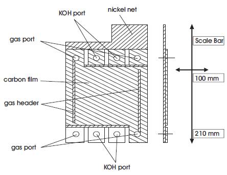
Figure 5. Gas diffusion electrode.
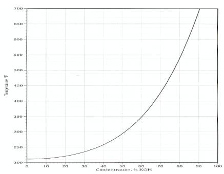
Figure 6. Effect of Potassium Hydroxide concentration on temperature.
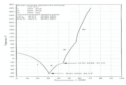
Figure 7. Limitation of concentration of Potassium Hydroxide on temperature [10]
Bearing this in mind it was important to check the KOH concentration being used in the cell. From the periodic table it was possible to determine the collective molecular weight of KOH by adding the individual atomic weights as set out in Table 1.
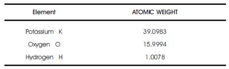
Table 1. The Molecular weight of KOH is 56.1056g.
1 mole solution is the molecular weight dissolved in 1 litre.
The electrolyte for the cell has a concentration of 7 mole which implies that 7 mole = 56.1056 x 7 g per litre. (weight/volume). 392.7392 g KOH per litre which implies that 392.7392 / 1000 cm3 = 39.3 g / 100 cm3 or 39.3 % (weight/volume).
From Figure 7 a concentration of 39.3 % gives a freezing point of approximately 36o . It may be possible to improve the freezing point of the KOH still further by using additives but the additive would need to be K+ or OH- friendly or electrically neutral so as not to impair the conductivity of the electrolyte.
Another major drawback of using potassium hydroxide (KOH) is that its viscosity decreases with temperature, this means it will penetrate and leak from cracks and minor pin holes more readily than sodium hydroxide (NaOH). The viscosity is improved by increasing the concentration. Potassium hydroxide also absorbs water decreasing its concentration, absorbs carbon dioxide from air and is very corrosive (may cause serious burns). KOH is incompatible with most metals and reacts vigorously with a wide variety of materials such as aluminium, zinc, brass, bronze and copper, making them completely unsuitable as materials for any components used as part of the systems construction. These factors were taken into account when designing the circulating system. KOH contact with components, (pumps, valves, and gauges) made from materials other than stainless steel, polypropylene or nickel resulted in their destruction. KOH is also extremely toxic/dangerous towards humans and should be handled with care. To prevent accidents protective gloves, clothing and glasses must be worn at all times, and the test bed should be positioned in a well ventilated area.
Figure 8 shows the test bed in operation. The storage gas supply for the test bed is provided by two 50 litre (volume) industrial bottles of compressed hydrogen and oxygen pressurised to 200 bar. A bottle of hydrogen gas has a distinct red cylinder and is purchased in Ireland from BOC Ireland.
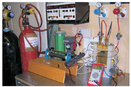
Figure 8. Operational Single Cell Test Bed.
The price varies greatly with the purity required, but the cell will operate efficiently on the normal lower priced hydrogen. As part of the test bed both cylinders were securely fitted to a mobile cylinder cradle to prevent them falling over and positioned with the test bed in a well ventilated area.
A regulator is a device that accepts gas at a high pressure and reduces it to a much lower working pressure. A good quality regulator is robust enough to withstand the full gas pressure within the cylinder and maintain effective control of the outlet gas, while also displaying the cylinder content. As an added safety precaution two multistage regulators similar to those illustrated in Figure 9, suitable for hydrogen and oxygen supply were fitted to each bottle. Multistage regulators are used because they reduce inlet pressure in two operating stage and are particularly suited to processes that rely on a constant accurate pressure. The first stage situated at the back of the regulator has a spring loading preset in manufacture. This reduces the cylinder pressure to a lower, medium pressure which is then passed through to the second stage.
This is operated by adjusting the pressure adjustment screw to give the required working pressure. The oxygen supply incorporates a flashback arrester but no flashback arrester was available for the hydrogen supply. These multistage regulators reduce the gas pressure at the cylinder outlet to 10 bar and maintains this pressure. A problem had been previously highlighted regarding cell performance variations being related to the volume of gas in the cylinder decreasing during use The main benefit of a multistage regulator is that regardless of cylinder volume the gas pressure for the cell will not be effected, so the cell can be left operating under load without the gas pressures falling off or requiring further adjustment once set.
For the cell to operate properly further precise and accurate pressure reduction was required. This function was performed by a specialised pressure reducer that safely reduced the O and H gases from 10 bar to 0.5 bar. The reducer used in this instance was a Minilabo 2 VH with needle metering valve, suitable for use with hydrogen gas and oxygen and manufactured by Tescom Europe, based in Germany.
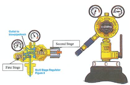
Figure 9. Multistage Regulator
Gas pressure flow-path for test bed is; Bottle 200 bar→ Regulator outlet, 10 bar → Reducer outlet to Cell, 0.5 bar.
Gas enters the reducer at 10 bar, the pressure in the reducer is released by screwing the hand-knob anticlockwise at the front of the reducer. The unit also has a winged cut-off valve; positioning the valve at 12o clock stops gas flow, slowly turning the winged valve vertical to the 3o clock position allowed gas to flow into the reducer. The outlet pressure is controlled by slowly turning the hand- knob clockwise until 0.5 bar is achieved and set as the system operating gas/oxygen pressure.
For added protection a one way valve was fitted inline to prevent any chance of potassium hydroxide reaching and destroying the reducer or multistage regulator.
The gases (hydrogen and oxygen) enter at the bottom of the cell, move vertically upwards through the fuel cell and exit diagonally at the top of the cell. At the point of exit, the gas flow through the cell for H2 and O2 is controlled by an adjustable purge valve that discharges into two small beakers.
The KOH electrolyte is the charge carrier of the cell, hydroxyl anions diffuse continuously from the cathode to the anode and water diffuses in the opposite direction. In an AFC most of the reaction water leaves on the anode (hydrogen) side, but a small amount of reaction water is removed via the circulating electrolyte loop. The formulation of water at the anode effects the electrolyte concentration of the cell and in non-circulating systems this resulted in a drop in cell voltage. The circulating system helps to replenish the electrolyte concentration in the cell and extend its operating life [9]. When the concentration of the electrolyte has diminished to the extent that output voltage is being affected the electrolyte in the reservoir is replaced with fresh concentrated KOH.
For the test bed 1.5 litres of KOH was stored in a reservoir/large glass beaker, before being circulated by a pump through an on/off valve into the bottom of the cell where it travels unimpeded horizontally through the cell and returns to the reservoir via another on/off valve. The initial system on, did not use the Eloflux flow system. With a circulating electrolyte a small amount of CO2 can be tolerated as a circulated liquid electrolyte has a very small capacity to absorb CO2. This prevents the formation of Potassium Carbonate, a crystalline deposit that can block electrode pores rendering the cell useless. This is important for vehicular applications as it means that a circulating system coupled with a simple absorbing tower (with soda lime or amines) can use air (which contains 0.03% CO2) as an oxidant.
2.3.1 Electrolyte StorageDuring normal testing the KOH was stored in a large Pyrex beaker. This was more practical for rapid heating-up of the cell in conjunction with the internal heating foils. It was found that the cell temperature could not be maintained at a preset figure once the electrolyte began to circulate. To solve this, the Pyrex beaker was placed on a hot plate and the electrolyte supply was heated, though not excessively to compensate for heat loss due to circulation. For general demonstration purpose however a polypropylene tank fitted to the test bed was used for KOH supply purposes. Polypropylene is resistant to potassium hydroxide and so a lot of the general fittings that come into contact with potassium hydroxide on the test bed are made from this material.
2.3.2 The Circulation PumpIn a fuel cell system the circulating electrolyte regulates the cell temperature, removes reaction water from the cell, replenishes the cell with fresh KOH, and cleans the cell of any carbonate deposits.
The pump used to circulate the electrolyte on the single cell test bed was the Iwaki Electromagnetic Metering pump, (shown in Figure 10).This pump was chosen because it does not draw the liquid electrolyte into the pump , protecting the moving parts from attack by a corrosive alkaline liquid.
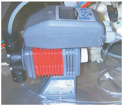
Figure 10. Iwaki Metering Pump.
The pump consists of a pump unit, a drive unit and a control unit all integrated into a single body. The Iwaki pump is a positive displacement pump that uses a diaphragm situated in a pump head constructed from glass fibre reinforced polypropylene (GFRPP) to draw and discharge the electrolyte. Some of the properties of polypropylene are; it is a lightweight semi rigid material, resists electrolytic attack, heat resistant and has excellent resistance to alkalis and acids.
2.3.3 OperationThe drive unit operates as a typical electromagnetic solenoid. When the solenoid is energised by the control unit the magnetic effect causes the armature which is connected to a PTFE faced diaphragm to move forward. This action decreases the cavity volume in the pump head and increases the pressure on the liquid inside forcing it out through the discharge valve to supply the system. De-energising the solenoid allows a strong spring to return the armature to the start position, pulling the diaphragm from the pump head. This action decreases pressure and increases volume within the pump head. Liquid electrolyte now flows from the reservoir under atmospheric pressure through the suction check valve and refills the head [12].
The discharge volume is adjusted in terms of stroke length and rate. The stroke length can be adjusted between 20% and 100%, the stroke rate can be set at 0 - 360 strokes per minute (spm), covering very minute flow rates. Manual mode on the controller allows for increases by single stroke per minute (spm) units [12].
The circulating system for the fuel cell test bed requires a flow rate of 5 lit/hour. This was set manually as follows. The capacity of EH-B20 PH type is 105 ml/min. The system requires 5000 ml or 5000/60=83.3333ml/min. For a stroke length at 100%, 83.3333/ 105 = 0.794 or approximately 80% giving 0.79365 x 360 = 285.7143 or 286 spm.
To design and develop a safe working fuel cell and operating system for commercialisation requires the expertise of various engineering and scientific disciplines such as, electrical, mechanical, chemical, computing, materials etc.
The fuel cell system is dynamic and the cell is affected by small changes in gas supply, pressure variations and temperature, requiring constant monitoring and control. An example of this is the cell temperature that is affected by the circulating electrolyte and impacts directly on the cells operating efficiency. In a fuel cell stack the circulating electrolyte cools, cleans and replenishes the cell but further experimentation using this test bed will indicate if a stationary electrolyte fuel cell similar to that used as part of the Apollo space program is a more efficient application.
Because fuel cells and their operating systems are still at the prototype stage, the cost of constructing a single cell test bed as described in this article is expensive. With the fuel cell alone costing E500, if this were to be applied to a vehicle requiring a 20 to 30 fuel cell stack the cost of the stack would be E15,000. This is not practical and so it is important that fuel cell development moves on to the next stage in an effort to reduce costs and promote mass production.
In Part II of this paper, we study an approach to cost reduction by considering the long term operation of an alkaline fuel cell in air rather than in Oxygen.
J M Blackledge is supported by the Science Foundation Ireland through the 'Stokes Professorship' programme.