
Figure1. Hybrid Cascaded Multilevel Inverter
This paper presents the design, development and performance of a hybrid cascaded multilevel inverter for fuel cell power conditioning system (PCS). Fuel cell generation systems in particular are expected to see increasing practical usage due to several advantages they offer over conventional generation systems. This article proposes a third harmonic injected phase disposition (THI-PD) pulsewidth modulation strategy for the hybrid seven level cascaded inverter that satisfies the required performance specifications of a fuel cell PCS. A particular advantage of this topology is that the modulation, control and protection requirements of each bridge are modular and it requires only a single dc source in each phase leg. For the cascaded multilevel inverter a variety of modulation strategies have been reported, with the most popular being carrier-based and space vector modulation (SVM). This paper focuses on the FPGA based THIPDPWM method for the hybrid multilevel inverter in PCS. Both the hybrid circuit topology and its control scheme are described in detail and their performance is verified based on simulation and experimental results.
Recently, hybrid cascaded multilevel inverters have gained popularity because it can produce more levels in the output voltage and minimize the distortion without increasing the number of switching devices and isolated sources. Traditionally, cascaded multilevel inverters (MLI) use multiple dc sources but nowadays energy storage elements have been used to replace some of the dc sources. Therefore a hybrid multilevel inverter employs a single dc source (fuel cell) per phase while the remaining dc sources are replaced by capacitors [1].The voltage regulation of the capacitor is the key issue and this is achieved by the switching state redundancy of the proposed modulation strategy. The advantages of this topology are higher output quality can be obtained with the reduction in switch count, lower control complexity and output filters can be remarkably shrunk or even eliminated. This hybrid inverter is especially suited for fuel cell driven electric vehicles and in applications that require energy storage to accommodate peak power demands. The control strategies of hybrid MLI can be classified into fundamental switching frequency and high switching frequency [2,3]. Further high switching frequency can be classified into space vector PWM and sinusoidal PWM. Sinusoidal PWM technique is classified based on modulating signal and carrier signal. According to modulating signal it is classified as pure sinusoidal PWM technique (PSPWM), Third harmonic injection PWM (THIPWM) and Dead band PWM (DBPWM).According to carrier signal it is classified as: Phase disposition (PD), phase opposition disposition (POD), alternative phase opposition disposition (APOD) and phase shifted (PS). This paper focuses on third harmonic injection PDPWM technique and it is compared with the conventional PDPWM technique. A comparative evaluation is made between PDPWM and THIPWM of hybrid cascaded seven level inverter suited for fuel cell applications. The advantage of THIPWM is that it improves the fundamental voltage without entering the over modulation range. Also, the total harmonic distortion (THD) of THIPWM is less when compared to PDPWM. Both the HMLI circuit topology and its control scheme are described in detail and their performance is verified based on simulation and experimental results.
Normally each phase of a cascaded multilevel inverter requires “n” dc sources to generate 2n+ 1 level. But the proposed hybrid cascaded multilevel inverter employs a single dc source (fuel cell) per phase to generate an equal step seven level output. The hybrid inverter consists of two h-bridges per phase as shown in Figure1. The main H - bridge (H1) is connected to a dc source (fuel cell) of value Vdc and the second bridge (H2) is connected to a capacitor whose value is maintained at Vdc/ 2. The output voltage of the first H-bridge is denoted by V1, and the output of the second H-bridge is denoted by V2 so that the output voltage of the cascaded multilevel converter is V(t) = V1(t) + V2(t). By opening and closing the switches of H1 appropriately, the output voltage V1 can be made equal to -Vdc , 0, or +Vdcwhile the output voltage of H2 can be made equal to Vdc/2, 0, or Vdc/2. Therefore, the output voltage of the inverter is a combination of Vdc and Vdc /2 which produces equal step seven level as shown in Figure 2. The switching state of Hybrid MLI is shown in Table.1
Figure1. Hybrid Cascaded Multilevel Inverter

Figure 2. Output Voltage Waveform of Hybrid Cascaded Seven Level Inverter

Table 1. Switching states of HCMLI
For the hybrid multilevel inverter several sinusoidal PWM techniques have been developed. The most popular and simple switching scheme for multilevel inverter is the multi-carrier PWM technique (MCPWM). For an N-level converter, N-1 carrier signals with the same frequency fc and peak-to-peak amplitude Ac are placed in such a way, that they occupy continuous bands between the positive and negative dc rail of the inverter. The voltage reference is continuously compared with each of the carrier signals. If the reference is greater than a carrier signal, then the active device corresponding to that carrier is switched on; and if the reference is less than a carrier signal, then the active device corresponding to that carrier is switched off. Related to the way the carrier waves are placed in relation to the reference signal, three cases can be distinguished:
This paper focuses on third harmonic injection PDPWM technique and it is compared with the conventional PDPWM. The proposed control scheme gives the lowest harmonic distortion in higher modulation indices when compared to other disposition methods. In this method carriers are in same frequency, amplitude and phases, but they are in different DC offset [4]. The modulating signal used is third harmonic injected sine waveform as shown in Figure 3. and this improves the gain of the pulse width modulator. There are six distinct carriers all in phase with one another and with the same magnitudes; the difference between the carriers is that they are all displaced by a set of dc offset. If the reference is greater than a carrier signal, then the active device corresponding to that carrier is switched on; and if the reference is less than a carrier signal, then the active device corresponding to that carrier is switched off [5].This method is derived from conventional sinusoidal PWM with the addition of a 17% third harmonic component to the sine reference waveform [5]. This is an alternative to improve the fundamental voltage without entering the over-modulation range. So, any carriers employed for this reference will enhance the fundamental by 15% without increasing the harmonics.
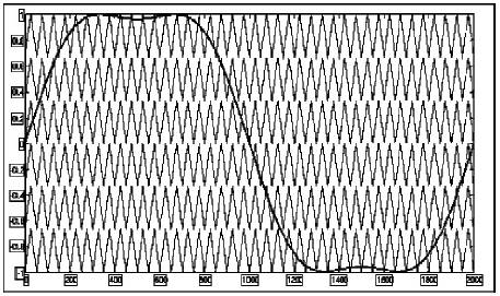
Figure 3. Modulating and Carrier waveforms for the THIPDPWM
To generate a seven - level output for the hybrid cascaded inverter, the eight gating pulses for the two Hbridges are given by comparing the reference signal with the six carrier signals. The reference signal is taken as third harmonic injected sinusoidal waveform and the six carrier signals C1, C2, C3, C4, C5, and C6 as triangular. The carrier signals are compared with the reference signal using a comparator and six output signals are produced. These signals are given as input to logic gate to produce eight output signals as shown in Figure 4. These signals are given to the eight switches of the two H-bridges (refer Figure1.) to produce a seven level output waveform [6].

Figure 4. Block Diagram for Generating gating Pulses using THI-PDPWM.
Fuel cell power generation is gaining importance because of its advantages like less environmental pollution, high efficiency, reliability, cleanliness and safe operation. Among the different types of fuel cells, the PEMFC is considered as a promising one as it has little start up time and their operating temperature is less, which is less than 100 degree centigrade.PEM fuel cell (refer Figure 5) is very simple and uses a polymer (membrane) as the solid electrolyte and a platinum catalyst. A fuel cell stack is composed of several fuel cells connected in series separated by bipolar plates and provides large power at higher voltage and current levels. The stack's voltage is determined by the number of cells, and the current rating is decided by the active area of the cells. The other parts of a fuel cell system are pumps, blowers, compressors, cooling system and a power conditioner unit as shown in Figure 6. The main purpose of the power conditioner unit is to regulate the fuel cell dc output so that it is suitable for connection to an electrical load. The literature shows a variety of power conditioning unit such as DC-DC power converters and DC-AC converters. For high power applications, it is essential to prefer multilevel converters. The advantages of multilevel architecture are modularity, high reliability due to redundant levels, low device rating and high efficiency. Hence, this paper proposes a hybrid cascaded multilevel inverter employing a single dc source in each phase for fuel cell applications.

Figure 5. Components of a Single PEM Fuel Cell
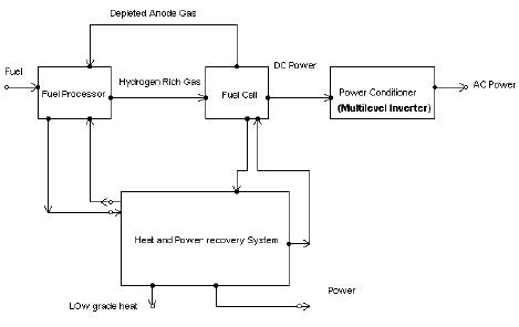
Figure 6. Block Diagram of a Fuel Cell System
The main advantage of fuel cell compared to battery is the unlimited power that can be produced as long as fuel is supplied. The fuel cells are modeled as ideal voltage sources with a series resistor. Figure 7 shows the V-I characteristics of a typical single cell operating at room temperature and normal air pressure. The characteristics curve is a plot of cell voltage versus cell current density. The difference between actual voltage and ideal voltage of a fuel cell represents the losses in the cell. The losses, which are also called polarization, originate from three sources I) activation polarization ii) ohmic polarization and iii) concentration polarization [7]. The reason for the occurrence of activation losses is the sluggish response of the electrochemical reaction of hydrogen and oxygen leading to nonlinearity. Ohmic losses is due to the flow of electrons through the electrolyte and electrodes. The concentration loss arises due to the change in the concentration of the reactants at the surface of the electrodes as the fuel is used. Along with the losses the polarization curve of fuel cell is also dependent on operating temperature. From the characteristic curve, it is obvious that the maximum power occurs in the ohmic region and therefore this region is used as voltage window for the power conditioner unit input. The voltage generated by a single fuel cell is about 0.7-0.8V at full output current, they are stacked in series to produce the required voltage level. For this work, 53 cells are stacked together to produce an output voltage in the range of 46- 50V and the polarization curve (Experimental Data: 46V, 22A) is shown in Figure 8. To obtain better results, an efficient power conditioner unit is essential.
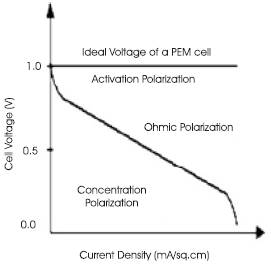
Figure 7. Ideal VI Characteristics of a Single PEM Fuel Cell.

Figure 8. Experimental Characteristic curve of a PEM Fuel Cell (No: of Cells: 53 and Output Voltage obtained: 46V, 22A).
The advantages of using hybrid multilevel inverter as power conditioner for fuel cells are:
The simulation results for THI-PDPWM based hybrid multilevel inverter for fuel cell power conditioning systems is shown in Figure 9 and for the conventional PDPWM is shown in Figure 10.
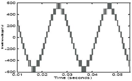
Figure 9. Line-line voltage of THIPDPWM based Hybrid MLI.

Figure 10. Line-line voltage of PDPWM based Hybrid MLI.
From the simulated waveform for hybrid multilevel inverter employing THI-PDPWM, the line-line output voltage waveform exhibits 13- levels whereas the conventional PDPWM shows only 11- levels for the amplitude modulation index (ma) of 0.95 and the carrier frequency (f ) equal to 3000Hz.
The work presents the comparison between third harmonic injected pulse width modulation technique and conventional PDPWM for a hybrid seven-level inverter which is proposed for fuel cell PCS. The investigation is made in terms of total harmonic distortion (THD) and fundamental line-line output voltage[8].The above comparison chart (refer Figures 11 & 12) shows THD values for different amplitude modulation index (ma) and fundamental line-line output voltage for different switching frequency for THIPWM and conventional PDPWM. For all amplitude modulation index values (ma) the THIPWM method shows lowest THD and the fundamental line-line voltage is higher in THIPWM than in conventional PDPWM.

Figure 11. Comparison of the fundamental line-line output voltage for THIPWM and Conventional PDPWM.
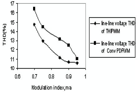
Figure 12. Comparison of THD values for THI-PD PWM and the Conventional PDPWM technique.
To experimentally validate the proposed Hybrid Multilevel Inverter, a prototype seven level inverter has been built using FSBB20CH60 smart power module (SMP) as switching devices with reference to Figure 1. The SMP uses IGBT as power switching device and it provides optimized circuit protection and drive matched to low loss IGBTs. System reliability is further enhanced by the integrated under-voltage lock-out and short-circuits protection. The high speed built-in HVIC provides optocoupler- less singlesupply IGBT gate driving capability that further reduce the overall size of the inverter system design. Each phase current of inverter can be monitored separately due to the divided negative dc terminals. Using SMP for the H-bridges as shown in Figure1. a single DC source (fuel cell 53 cells) for bridge1 was used for the hybrid cascaded MLI and the other source being capacitor (4700uF/100V -2nos in parallel) to generate seven levels. The gating signals were generated using FPGA processor based on THIPDPWM techniques and the output power level of the inverter is 850W. The gating signals for the switches are shown in Figures.13, 14. The experimental output waveform for Hybrid Multilevel Inverter is shown in Figures15, 16.
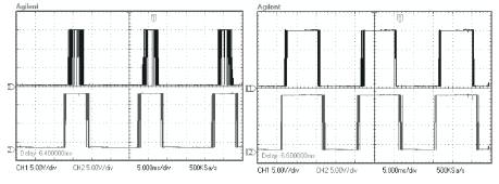
Figure13. Pulse Pattern for the First Bridge (H1 ).
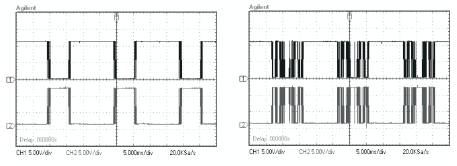
Figure 14. Pulse Pattern for the Second Bridge (H2 ).
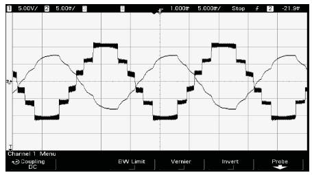
Figure15. Experimental Equal 7-level Output Voltage and Current Waveform for the Hybrid Inverter with R=50 & L=36mH.

Figure16. Line voltage for Hybrid MLI showing 13- levels.
From the simulation and experimental results, several distinct features of the seven level hybrid inverter for fuel cell PCS with THIPDPWM scheme from the aspect of line voltage can be identified. The line voltage yields better spectral performance for THIPDPWM compared to the conventional PDPWM and this reduces the need for output filter. At high modulation index the proposed PWM technique introduces the lowest line voltage total harmonic distortion (THD).Therefore it is suggested that the hybrid multilevel inverter using the proposed THIPDPWM is well suited for high power fuel cell modules. A single dc power source and two H-bridges for each phase have been used as a good tradeoff between performance and cost. The THIPDPWM yields a THD of 7.23% for ma = 0.95 and mf = 20 and it is verified experimentally.