(1)
The urgent need of electricity everywhere and anywhere prompt everyone to search for it with more benefits and profits. Simultaneously the same search should end up with good choice of energy production because the conventional source of getting electricity tends to reduce vigorously now a days. Sooner or later the options go for renewable sources by which less pollution encounters while more production dominates. Here is the discussion about the analysis of permanent magnet synchronous generator used in small scale wind generators with its suitable modeling in Simulink /Matlab.
Small scale wind generators are becoming popular in meeting the load demand enormously both in metropolitan and rural areas wherever the network grid is not available. It can be intended to use either beneficially to a mass community or private use. The national average per capita electricity consumption is 778.63 kW per month according to the recent statistics. Small wind turbine systems, with a capacity ranging from 50 W to 10 kW and rotor diameter ranging from about 0.5 m to 7 m, can be primarily used in small scale wind generators with battery charging. These applications include energy supply for houses like lighting, television, refrigerator and hospitals, farms, telecommunications, navigation, etc. Wind energy systems can also be operated in parallel with diesel sets or solar PV systems.
The organization of the paper is made in such a way that it begins with the introduction and Section 1 is devoted for explaining the different types of wind electric generators used in variable and fixed speed wind turbines. The basic mathematical equations are used in constructing the model and the relevant Simulink blocks for those equations are briefly discussed in Section 2. Last section includes the results and conclusion with extension of work to be carried out in a real time with references cited.
Modern Wind Turbine Generators (WTGs) employ power electronics and real and reactive power controls allow the wind power plants to have much better steady‐state and dynamic performance compared to the wind power plants of the past. For reliability and cost reasons, it is very important to properly represent steady and dynamic characteristics equally in small and large scale power production. Generally there are four types of wind turbines widely used in wind mill sector. They are Induction Generator, Wound Rotor Induction Generator with adjustable external rotor resistance, variable speed Wind Turbine Generator with Doubly Fed Induction Generator, variable speed wind Turbine Generator with full conversion power converter.
Induction Generator usually needs reactive power from the utility grid, to supply that power switched capacitors which are connected in parallel with each phase of the winding. The switching on and off the capacitors can be done automatically according to the operating point of the Induction Generator. When the Wind speed increases, the generated power also increases and ultimately the reactive power drawn from the utility also goes higher and hence it is usual practice to make the induction generator to run in unity power factor [1]. The second type is a wound rotor induction generator with adjustable external resistors. Wind turbine is able to produce only when the rotor speed is above the synchronous speed. As soon as the wind speed increases, the input aerodynamic power increases ultimately increasing the rotor slip and electrical output power. The rotor resistance is adjusted until the turbine output becomes constant. The blade pitch angle is another parameter to control the aerodynamic power generated for safe operation.
The third type with variable frequency power converter is set to carry only 30% of slip power and hence it is of small size. The rotor power flows from the grid line to the rotor winding while the rotor speed is below synchronous speed and when it crosses the synchronous speed, the rotor power intend to flow from rotor winding to the lines. In the last type, the electric machine used may be either an induction machine, wound field synchronous generator, or a permanent magnet synchronous generator. The power converter used is capable of controlling real and reactive power separately.
Wind is created by unequal heating of earth's surface by sun. Wind turbines convert the kinetic energy in wind into clean electricity. When wind spins, the wind turbines blades, rotor captures the kinetic energy of the wind and converts it into rotary motion to drive the generator. Most turbines have automatic over speed-governing systems to keep the rotor from spinning out of control in very high winds. A small wind system can be either connected to the electric grid through or it can be of standalone (offgrid). This makes small wind electric systems a good choice for rural areas that are not already connected to the electric grid.
Small wind turbines are generally horizontal axis type and have an upwind rotor directly coupled to a variable speed electric generator. Power modulation, rotor speed and orientation controls are achieved by passive aerodynamic techniques. These turbines can have a DC or AC generator. There are three different types of AC generators generally used in small scale wind generators namely Synchronous Generator, Asynchronous or Induction Generator and the Permanent Magnet Generator.
Schemes of power generation based on Permanent Magnet Synchronous Generators (PMSG) and induction generators are getting close attention in wind power applications because of their specific qualities such as ruggedness, low cost, manufacturing simplicity and low maintenance requirements [2]. Having characterized by weak inductances, elevated torque and weak inertia permanent magnet synchronous generators are less in use in wind sector plants but plenty of reasons to make use of them in small scale wind generators with the advancement of power electronics.
As non-polluting and continuous source of electric power, wind energy has been the right option for safe power production now a days. Among the commercially available wind turbine generators, it is found that direct drive, grid connected generators or even standalone generators mostly uses Permanent Magnet Synchronous Generator (PMSG) because of its greater performance and efficiency with less maintenance now a days with minimum losses encountered [3].
When the PMSG generator is connected to the grid, the speed is determined by the grid frequency and is constant. So, if the torque to the generator is increased due to sudden blow of wind, the generator will produce electromagnetic force to resist an increase in speed. However IG allows a small change of speed with the change of torque going to the generator and lower stresses/tear and wear of the drive train. As the IG and the PMSG machine have similar stator, the cost difference is mainly due to the rotor. Though the cost of PMSG is higher compared to induction generator for the same power rating, PMSG generators have higher efficiency.
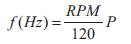
Permanent magnet synchronous generator is a generator where the excitation field is provided by a permanent magnet instead of a coil. Synchronous generators are the majority source of commercial electrical energy. They are commonly used to convert the mechanical power output of steam turbines, gas turbines, reciprocating engines, hydro turbines and wind turbines into electrical power into the grid. They are known as synchronous generators because ƒ the frequency of the induced voltage in the rotor (armature conductors), is directly proportional to P, the number of permanent magnet stator poles (almost always an even number). The constant of proportionality is, RPM/120 where RPM is the revolutions per minute of the rotor (or angular speed);
Permanent magnet generators neither requires a DC supply for the excitation circuit, nor do they have slip rings and contact brushes. However, large permanent magnets are costly which restricts the economic rating of the machine. The flux density of high performance permanent magnets is limited. In these permanent magnet alternators the speed is directly proportional to the output voltage of the alternator. The physical modeling of wind turbine with permanent magnet synchronous generator is depicted in Figure 1 with its output ac voltage converted into DC by bridge rectifier, again to ac by means of DC/AC inverter with IGBT as switching device and lastly to grid through Point of Common Coupling, (PCC).
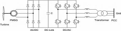
Figure 1. Wind Turbine connected with inverter and grid
From the available literature relating to the wind turbine technology it is found that the cumulative power available in the wind is generally obtained by this equation
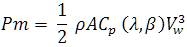
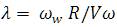
where ρ is the air density, A the area covered with turbine blades, Vw the wind speed, Cρ (λ,β) the turbine power coefficient, is a function of pitch angle β of rotor blades and of the tip speed ratio λ, which is the ratio between blade tip speed and wind speed value upstream of the rotor, given by
and often Cρ is been taken as 16/27 and is equal to 0.59 called Betz Limit [4, 5].
Since per phase equivalent circuit is valid only for steady state condition in adjustable or variable speed drives the transient behavior has to be taken into consideration and high performance drive control like vector or field oriented control [6,7] based on dynamic d-q model of the machine is widely used. According to Park transformation theory, the change of variables namely voltages, currents and flux linkages associated with the stator windings of synchronous machine can be replaced by variables associated with fictitious windings rotating with rotor synchronous speed. The stator variables are transformed to a synchronous rotating reference frame fixed on the rotor eliminating the time varying inductances.
The 3-ϕ stationary frame as-bs-cs variables are transformed into two phase stationary reference frame first and then to synchronous rotating reference frame d-q and vice-versa [8]. PMSG can be modeled using synchronous reference frame in state equation form given as
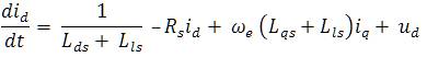
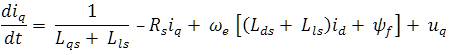
where subscripts d and q refer to the physical quantities that have been transformed into the d-q synchronous rotating reference frame, R, the stator resistance, Ld and Lq are the inductances of the generator on the d and q axis, LId and LIq are the leakage inductances of the generator on the d and q axis, respectively, ψ is the permanent magnetic flux and ωc is the electrical rotating speed of the generator, defined by

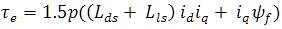
The expression of electromagnetic torque [9] concludes the mathematical modeling of PMSG,
The PMSG is modeled with the help of derived mathematical equations in MATLAB/Simulink. The parent system includes two main blocks namely Wind Turbine and PMS Generator. The inputs given to wind turbine block includes generator speed, pitch angle, wind speed, air density and rotor radius as in Figure 2. The wind speed is set as an average of 9m/s constantly and has been subjected to change between 5m/s and 12m/s by using the saturation block. The outputs of this block are mechanical torque Tm, mechanical power Pm, and power co-efficient Cp and tip speed ratio λ. The mechanical torque is been multiplied with gain to get an electrical torque. The electrical torque developed is the main source of input to obtain the rotor speed of the PMS generator and the phase currents in rotor terminals.
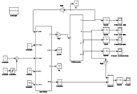
Figure 2. Main block of wind turbine with PMSG
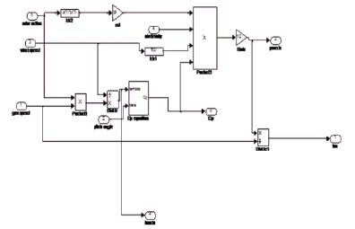
Figure 3. Block used to calculate Cp
The wind turbine block constitutes the sub system in Figure 3 which calculates the performance co-efficient by giving two inputs, the pitch angle β and the other tip speed ratio λ.
The abc quantities obtained from dq axis after the Park's transformation is shown in Figure 4.
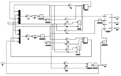
Figure 4. Subsystem of PMSG
The various scopes obtained after simulation have been depicted in corresponding figures numbered from Figure 5 to Figure 13. The power output fluctuates between 750 Watts to 800 Watts as in Figure 5. The per unit value of reactive power output ranges from -6 to 6 as in Figure 6 and Figure 7. Per phase rotor current is depicted in Figure 8. From the simulated outputs as in Figure 9, proportional change is observed in performance co-efficient Cp-3 which drastically reduces when tip speed ratio λ comes to 3.4x10⁻³ when time elapses. From Figure 10 and Figure 11, it is clear that the mechanical torque starts from 2400 N/m2 and peaks up to 5700 N/m2 for the rotor speed around 750 rpm. Likely the output voltage starts from 20V and drastically reduces to 4V which is shown in Figure12 and Figure 13. The power output fluctuates between 800 Watts 1000 Watts respectively.
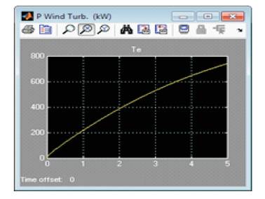
Figure 5. Power @ wind turbine
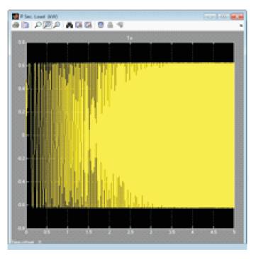
Figure 6. Reactive power @ Secondary Load
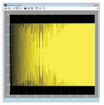
Figure 7. Reactive power@ main Load
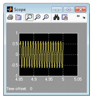
Figure 8. Rotor phase current
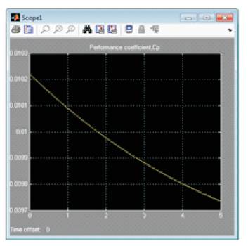
Figure 9. Calculation of Cp
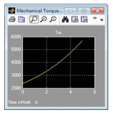
Figure 10. Mechanical Torque
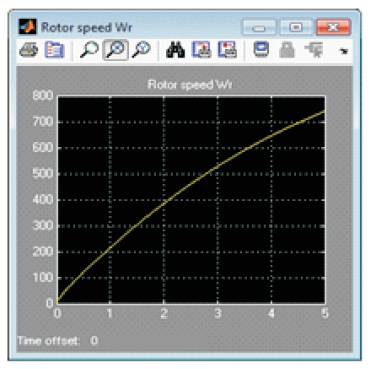
Figure 11. Rotor Speed ωr
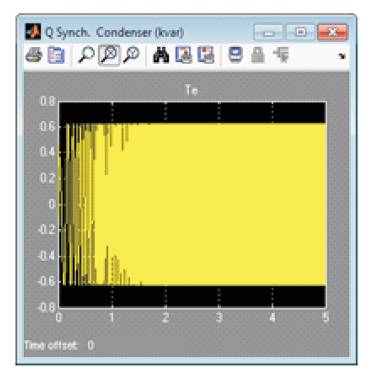
Figure 12. Output Voltage
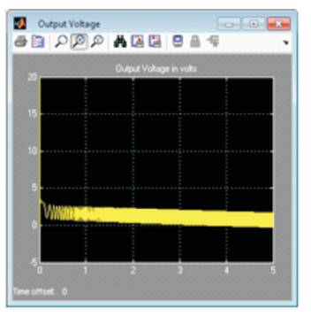
Figure 13. Q @ Synchronous condenser
Compared to doubly fed induction generator which is also suited for variable speed operation, permanent magnet synchronous generators are cheap and sturdy for small scale wind power generation. With the modeling of PMSG completed, we are able to obtain the large amount of power output nearly equals 1 kW in simulation. It inspires to construct real time implementation of wind electric generator with permanent magnet AC generator clubbed with photovoltaic panels. The working of WEG seems to fit well when PMSG is used. It is at this juncture that a novel idea is conceived whereby the local load demand can be met with the test set-up integrating with the diesel generator and a battery backup.
These can be used to generate electricity for meeting the major load demand and can feed the excess energy to the grid. It will also help to earn revenue and also improves the tail-end supply of electricity to the utility grid.