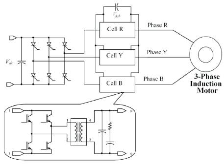
Figure.1. Basic Converter Topology.
Normally, high power voltage source inverters are very common in industry and they need to provide sinusoidal output to the load for proficient operation. Sinusoidal wave output can be obtained in inverters by adopting various modulation techniques, which increases the switching frequency of the inverter elements like IGBTs (Insulated-gate bipolar transistor) and Power MOSFETs (Metal-Oxide-Semiconductor Field-Effect Transistor), which are having limited power handling capabilities. In case of moderate to high power output from the inverter, SCRs or GTOs (Gate Turn-off thyristor)(Silicon-Controlled Rectifier) need to be used as inverter switching elements. These devices are having limited switching frequencies making the inverter operation impossible using the high frequency modulation techniques. This results in an output with rich harmonic content. The latest multilevel inverters can be used to overcome these problems. But the circuit is very complex and also requires isolated power supplies to feed the inverter. In the proposed project, a low frequency square wave inverter using SCRs is operated along with a series connected pulse width modulated inverter, in each phase is designed. The 3-phase SCR inverter basically works as a voltage source inverter producing square wave output. The series compensator used in each phase produce only the desired harmonic voltages to make the net output voltage sinusoidal, with small PWM switching harmonics only. The series compensators are designed using the IGBTs, forming a bridge inverter configuration.
Power electronics has been widely used in various applications since it was born. The three-phase inverter, which converts DC voltage/current into three-phase ac voltage/current is one of its most important and popular converters. It has been widely used in Motor drives, AC Uninterruptible Power Supplies (UPS), Induction Heating, AC Power Supplies, Active Power Filters and static VAR generators or compensators, etc. There are two types of traditional inverters, namely voltage source inverters and current source (fed) inverters. However, both inverters have some conceptual barriers, which will be discussed in detail later. The newly presented Elimination of Harmonics in a Square-wave inverter by using series compensators for medium voltage applications [1] has some unique features and it can overcome some of these limitations [2]. The purpose of this work is to eliminate harmonics in square wave inverter for medium voltage application.
An important factor in industrial progress in the past five decades has been the increase in sophistication of factory automation which has improved productivity many-fold. Manufacturing lines typically involve a variety of variable speed motor drives which serve to power conveyor belts [3] robot arms, overhead cranes, steel process lines, paper mills, and plastic and fiber processing lines [4] Prior to 1950's all such applications used DC motor drive since AC motors were not capable of smoothly varying speed since they are inherently operated synchronously or nearly synchronously with the frequency of electrical input. To a large extent, these applications are now serviced by what can be called general-purpose AC drives [5]. In general, such AC drives often feature a cost advantage over their DC counterparts and, in addition, offer lower maintenance, smaller motor size, and improved reliability [6]. However, the control flexibility available with these drives is limited and their application is, in the main, restricted to fans, pumps, and compressor types of applications where the speed needs to be regulated only roughly and where transient response and low-speed performance are not critical.
More demanding drives used in machine tools, spindles, high-speed elevators, dynamometers, mine winders, rolling mills, glass float lines, have much more sophisticated requirements and must afford the flexibility to allow for regulation of number of variables, such as speed, position, acceleration, and torque. Such high performance applications typically require a high-speed holding accuracy better than 0.25%, a wide speed range of at least 20:1 and fast transient response, typically better than 50 rad / s, for the speed loop
The proposed topology has evolved from the typical series compensating devices like the Unified Power Quality Conditioner (UPQC), Digital Video Recorder (DVR), etc. The main square-wave inverter is solely responsible for the fundamental voltage [7]. Each phase has series connected single-phase PWM inverter that produces only the required harmonic voltages as shown in Figure1. These three single-phase cells normally have common DC bus voltage. Usually, the value of this common DC bus voltage is less than that of the main square-wave inverter. This justifies the PWM mode of operation of the series inverter [2]. Figure.1 shows the basic converter topology where the common bus DC voltage is generated separately.
Figure.1. Basic Converter Topology.
Alternatively, a small amount of controlled active power has to be drawn by the series inverters to control this DC bus voltage [4]. The desired harmonic voltages are injected to the line using three single phase transformers, as shown in Figure. 1.
Small capacitor and resistor networks at the output of the single-phase transformers remove the switching harmonics. In this paper, natural open-loop control of this series compensator dc bus voltage is proposed without drawing any active power at fundamental frequency. A separate active DC voltage source is also not required here. The active power drawn at harmonic frequencies regulates the DC bus voltage of the series compensator.
A per-phase equivalent circuit of this proposed system is shown in Figure 2. The load could be a motor with equivalent leakage impedance RL , LL , and the sinusoidal back EMF EL at fundamental frequency. It may also represent the grid voltage [8] EL at fundamental frequency and the series impedance RL and LL
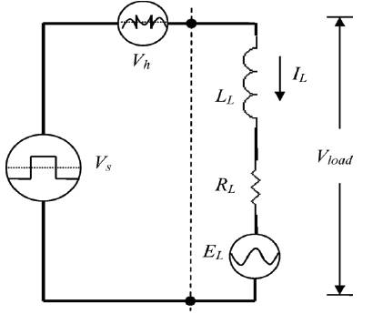
Figure 2. Equivalent Single-Phase circuit of proposed converter with load.
In the proposed topology, there is no separate source to maintain this desired value for the series compensator DC bus voltage. Let us assume that the modulation depth (m) of the nth harmonic component of the series compensator is as follows:

nth harmonic output component of series compensator can be defined as:
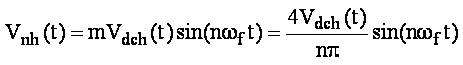
Vdch(t) is the DC bus voltage of the series compensator at any time 't'. The nth harmonic equivalent circuit of the converter with load is shown in Figure 3.
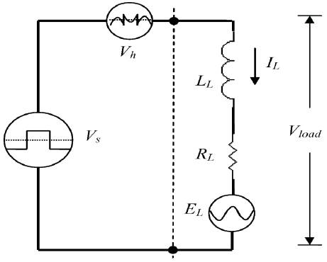
Figure 3. Single-phase equivalent circuit of the harmonic voltages only.
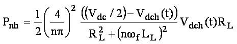
Assuming that the dynamics of Vdch(t) is very slow, the average active power (Pnh ) absorbed by the series compensator due to the nth harmonic voltage is as follows:
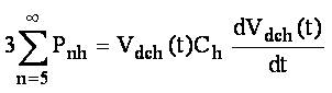
Neglecting losses of DC bus capacitor, the dynamical equation of Vdch(t) can now be written as follows:
Fundamental load current does not affect the DC bus voltage balance as there is no fundamental component of voltage at the output of the series compensator [9]. The block diagram of basic switching control strategy for the topology is shown in Figure 4.
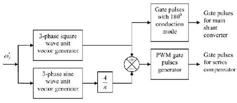
Figure 4. shows the Gate pulses generation for the basic converter topology which is in the Figure.1
The Compensator Reference Voltage waveform which is fed to the system is shown in Figure 5.
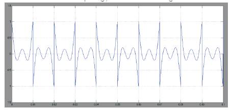
Figure 5. Compensator reference voltage
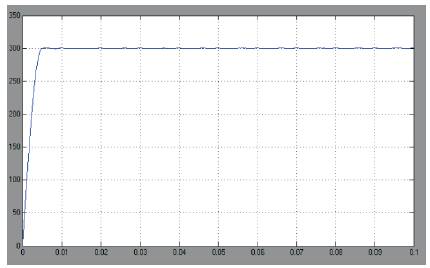
Figure 6. DC bus voltage
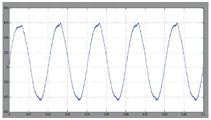
Figure 7. Load current in steady state
DC bus voltage at 11th harmonic is shown in Figure 8
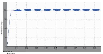
Figure 8. DC bus voltage at 11th harmonic cell (in volt)
Figure 9 shows the spectrum analysis of the output voltage with the THD of 4.55% Load voltage waveform in steady state condition is shown in Figure 10. The spectrum analysis of the output voltage with THD of 3.79% is shown in Figure 11. The stator current, speed curve and electromagnetic torque characteristics of the Induction motor which is connected to the system are shown in Figure 12, 13 and 14 respectively.
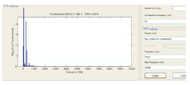
Figure 9. Output current THD
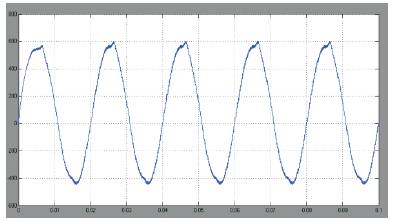
Figure 10. Load voltage in steady state
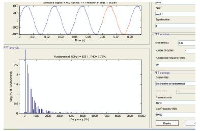
Figure 11. Output voltage THD
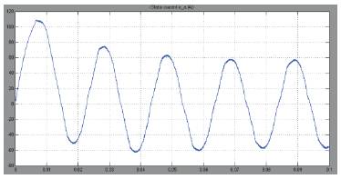
Figure 12. Stator current of induction motor
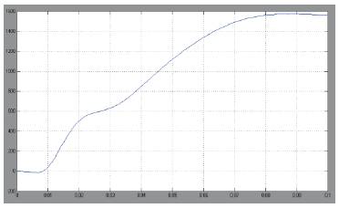
Figure 13. Speed curve of induction motor
Figure 14. Electromagnetic Torque characteristics of Induction Motor.
In this paper, an open-loop natural control of voltage source inverter has been proposed mainly for high-power applications. The main square-wave inverter is built with high-voltage low switching- frequency semiconductor devices like Integrated Gate Commutated Thyristors (IGCTs). The series compensators are IGBT-based inverters. The series compensators produce only the desired harmonic voltages to make the net output voltage sinusoidal. For medium-voltage application, several compensating PWM (Pulse Width Modulation) inverters are connected in series. Each cell compensates one particular harmonic only; as the order of harmonics increases, the required DC bus voltage level drops. This enables to exploit higher switching frequency for higher order harmonic cell. For variable-speed drive applications, the magnitude of the fundamental output voltage should be controlled by regulating the DC bus voltage of the square-wave inverter.