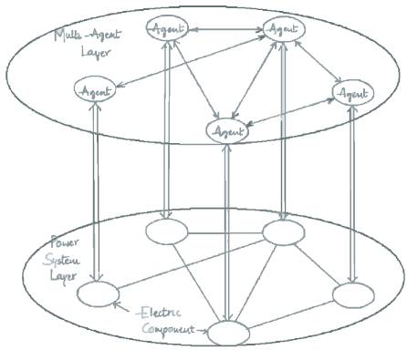
Figure 1 Hierarchy of a reconfiguration model
This paper presents a novel, completely decentralized Multi Agent System based reconfiguration methodology for Shipboard Power Systems. The objectives of the approach considered are: to design an Multi Agent System based reconfiguration structure, an algorithm that can break an arbitrary mesh structured Multi Agent System into tree structure to avoid redundant information accumulation problem and to develop a completely decentralized reconfiguration methodology. Software has been developed using C for the above work.
Shipboard Power Systems (SPS) are power systems that supply electric power to the weapons, communication, navigation, and operation systems onboard for US Navy ships. In the event of battle, part of the SPS may not be available due to the damage. Under such conditions it is essential to keep the ship operational for the completion of mission of the ship. This can be achieved by supplying the vital loads continuously, which is possible through the reconfiguration of SPS wherein the loads in the power system are restored based on the load priority[16]. Compared to the terrestrial power systems, the SPS has unique characteristics.
Based on the unique characteristics of the SPS, some reconfiguration methods have been proposed. But most of the reconfiguration methodologies, which are proposed, are centralized. In a Shipboard Power System's centralized reconfiguration approach, a single point of failure may occur if the system lacks redundancy. Moreover the communication in the centralized system may require large bandwidth. In this paper, a completely decentralized MAS based reconfiguration methodology is proposed for Shipboard Power Systems, which is not topology dependent and is applicable to the mesh structures as well.
In completely decentralized MAS with loop(s), a message that starts from an agent in the MAS may reach the agent from which it initially originates through the loop. This looping problem may cause a Redundant Information Accumulation (RIA) problem in MAS. In this paper, a decentralized spanning tree algorithm is proposed to avoid the RIA problem in MAS with loop(s).
The paper is organized as follows. Section 2 discusses the loopholes faced by the centralized approach and introduces decentralized approach. Section 3 describes Multi Agent System applied to decentralized systems and addresses the Redundant Information Accumulat ion (RIA) problem for completel y decentralized MAS with loop. Section 4 proposes a solution to the RIA problem. Section 5 presents an illustration of Shipboard Power System for reconfiguration using MAS technology. Finally the whole paper is summarized and conclusions presented.
P. Ravi Babu et al [6] presented a method to solve the over loading problem and service restoration strategies for affected zones due to fault in a three feeder distribution network which deals with the estimation of load changes through feeder reconfiguration using the heuristic search technique. This method was based on minimum number of switching and minimum total I2R losses.
P. Ravi Babu et al [7] presented a new approach for service restoration, system reconfiguration of a four feedertwenty bus IEEE distribution system solved by heuristic search through best first search armed with problem specific function to guide the search. The objective of the approach considered was a two fold, to restore the service to the affected loads due to fault and balancing loads under overloading conditions through optimal reconfiguration.
Butler and Ehsani [8] discussed new techniques which will reduce manning requirements and increase the reliability of continuous service through automation of functions related to the ship's electrical system. Its functions included monitoring and control, automated system failure analysis and identification, automated intelligent system reconfiguration and restoration, and selfoptimizing power system architecture under partial failure.
Zhang et al [9] presented modeling shipboard power systems with PSpice. The detailed model for system components like generators, cables, loads, etc. was provided. Transient simulation results were presented.
Zhang et al [10] presented a PSpice methodology for modeling SPSs. Transient simulation results were also presented, as, to conduct system studies on SPSs, an effective simulation tool was required. PSpice is a very robust analog/digital circuit simulator, but it is rarely used in power system studies.
Adediran et al [11] made the study of a shipboard power system consisting of three generators. It was sought to be understood in two ways. One was through modeling and the other through fault analysis. Some conclusions were drawn on the behavior of the system.
Adediran et al [12] presented modeling of the SPS. The shipboard power system was designed as ungrounded delta system to achieve system survivability in the event of a single line to ground fault. Another design feature to ensure survivability and reliability of the system was protection. The modeling of the Navy SPS protective devices was also discussed as they pertain to SPS survivability and reliability. Short circuit fault scenarios were performed to study protective device coordination and system survivability.
Butler et al [13] presented the results of the analysis of three popular simulation tools, ATP, PSpice and Saber for transient simulation of Shipboard Electric Power Systems (SPSs). The results suggested that ATP was a good tool for generating detailed component models and calculating model parameters directly from standard specifications and ratings of the equipment. PSpice and Saber had an excellent graphical interface for building complex SPSs and flexibility in establishing monitoring points and processing output data.
Butler et al [14] presented a new method to reconfigure the network to restore service to unfaulted sections of the system. The problem was formulated as a variation of fixed charge network flow problem. The method was illustrated using various case studies on a small power system with similar topology to a shipboard power system.
Srivastava et al [15] proposed a network reconfiguration technique for restoring a naval power system resulting from battle damage or system faults. The methodology developed determined whether the loads that lost supply are restorable. When considering loads, it gave precedence to high priority loads. It also determined if there was any violation of current constraints of any cables and voltage constraints at load nodes.
Butler et al [16] have developed a method to restore maximum loads in SPS based on the fixed-charge network flow method. An enhancement to their method was proposed to handle priority for loads and paths while restoring service in SPS. The proposed method was illustrated with some case studies on a simplified SPS.
Butler and Sarma [17] presented an automated selfhealing strategy for reconfiguration for service restoration in naval shipboard power systems. The proposed method was illustrated on a system developed based on a typical surface combatant ship.
Srivastava and Butler[18] presented an automatic rulebased expert-system method for reconfiguration of electric-power systems on naval ships which determines the control operations necessary to restore power supply to de-energized loads after battle damage or cascading faults.
Srivastava and Schulz[19] proposed a reconfiguration technique for SPS in which graph theory has been applied to represent the shipboard power system and all possible islands formed due to the fault are found with their load and generation capacities along that path. Then binary particle swarm optimization was applied to optimally reconfigure the set of loads satisfying the operational requirements and priorities of load.
Srivastava and Butler [20] put forward a new automated probabilistic predictive self-healing methodology to determine reconfiguration control actions of SPS. Implementation of these actions lead to less damage caused by a weapon hit and can considerably improve a ship's chances of surviving an attack. The probabilistic approach entailed three major functions: weapon damage assessment, pre-hit reconfiguration before a weapon hit for damage reduction and reconfiguration for restoration after a weapon hit to restore de-energized loads.
In a centralized reconfiguration system without redundancy, if the central controller fails, the entire reconfiguration system fails. This is the single point of failure problem for centralized solutions. The central controller in a centralized reconfiguration approach collects data from the entire power system, analyzes the collected data, and then makes the reconfiguration decisions. When the number of electric components increases, or the topology of the power system becomes complicated, the computational burden of central controller increases. It may slow down the reaction time of the central controller and decrease the performance of the reconfiguration system. For a large power system with numerous electrical components and sensors, the amount of communication bandwidth required for operation of a central controller will be very high and costly.
The decentralization characteristic of the reconfiguration methodology makes the reconfiguration methodology immune to the single point of failure. The computation associated with the reconfiguration is distributed throughout the agents in the MAS, so that the reconfiguration system is scalable when the number of components in the power system increases or the topology of the power system becomes complicated. Finally, the agents in the developed MAS can communicate with a limited bandwidth.
Multi Agent System (MAS) is a system composed of agents, where each agent is an imaginary entity capable of executing a specified function[17]. Each agent here is associated with one electric component in the power system, if two electric components in the power system have connectionwith each other, these corresponding agents in the MAS are defined as the neighboring agents of each other. The agents in MAS are limited to communicate only with their neighboring agents. Each agent in the MAS works independently and autonomously. There is no dominant agent or central controller in the MAS [18].
MAS is thought of as an imaginary layer, similar to the power system layer as shown in Figure 1. The lower layer is the power system layer. The power system consists of different electric power components, such as generators, transformers, motors, circuit breakers, and so on. The upper layer is the MAS layer, in which each agent is associated with a major component in the power system layer. An agent in the MAS can exchange information with the corresponding electric component in the power system layer. For example, if a generator is connected with a circuit breaker in the power system layer, the corresponding generator agent and circuit breaker agent are defined as neighboring agent of each other. So the topology of the MAS layer is similar to that of the power system layer, as shown in Figure 1.
Figure 1 Hierarchy of a reconfiguration model
An agent in the multi-agent layer is restricted to only communicating its neighboring agents to assure that the system works as a decentralized system. This communication architecture makes the system less dependent on the topology of an SPS. Meanwhile, this setup also decreases the communication burden within the system.
In completely decentralized MAS, each agent communicates only with its neighboring agents. The agents exchange the information with each other by sending/receiving message to/from their neighboring agents. Whenever an agent receives a message from one of its neighboring agent, it generates a message and forwards it to all other neighboring agents. Whenever there is a loop in the MAS, the message may go back to the agent where the message initially originates. This is the information looping problem in the completely decentralized MAS. This looping problem known as Redundant Information Accumulation (RIA) happens in any completely decentralized control networks with loop(s) [19]. RIA is like a positive feedback loop in a traditional control system and makes the message flow in the MAS unstable. Therefore, a spanning tree algorithm has been proposed to solve the RIA problem in MAS with loop(s).
In this section, an algorithm is put forward to solve the RIA problem in completely decentralized MAS. This algorithm is scalable, generic and applicable to MAS with any dth topology. The overhead of the message will not increase when the size the of the MAS increases. So the bandwidth requirement for the MAS can be reduced and will not exceed a certain limit. A flowchart is presented in the Figure 3 depicting the binary spanning tree algorithm. The algorithm can break the connections between agents in the MAS. However, it does not affect the connections between the electric components in the power system. In graph theory, the tree is a graph in which any two nodes are connected by exactly one path. There is no loop in a system with tree topology. In a rooted tree, one node is the root node in the graph. The root node takes its neighboring node(s) as its children node(s). If node A is a child node of node B, then node B is a parent node of node A. If a node has node(s) other than the parent node, it takes those node(s) as its children node(s). A node with no children node(s) is defined as a leaf node[5].
A graph with loop(s) can be spanned into a tree topology by breaking the loop(s) into a graph. The spanning tree algorithm is used to eliminate the loop(s) in a ring or mesh structured network by breaking the loop(s) in the network.
1. Consider a MAS with n agents. The agents are similar to nodes in a binary tree structure.
2. Each agent has a separate UID. UID is a number that can be used to identify an agent in MAS. Let the UIDs be represented by i where i= 1, 2, 3,…n. UID is a unique identifier of an agent that actually represents the power capacity of the corresponding electric component.
3. An agent with highest power capacity is elected as the root.
1. Comparison of the UIDs of agents in the system to initialize the agent with the highest UID as the root agent.
2. When an agent receives a UID from its neighboring agent, if received UID is higher than its own UID and all UID s it received previously, the agent takes the sender agent as a parent agent and the sender agent takes this agent as its child agent. Also, the agent forwards the received UID to its neighboring agent.
3. In this way, the highest UID in the MAS will be spread out through the MAS and each agent receives the highest UID at least once. In limited time, the each agent in the MAS knows the highest UID in the MAS and the agent with the highest UID is elected as the root agent.
4. Now, a tree structure is generated with root, parent and child agents.
5. In the generated tree structure, it is made sure that parent agent and children agents are defined for each agent other than for root and leaf agents. A rootagent is the one without parent agent and leaf agent is the one without children agents.
6. The information flow in MAS is ensured in such a way that no child has two or more parent agents concerned to it.
7. After the path is designed as per the principle, there is a confirmation check in the path both in upward direction i.e., from leaf to root and downward direction i.e., from root to leaf.
8. This will detect the links, which are to be removed to make the mesh into a tree structure.
Consider an example system for illustration of spanning tree algorithm. By applying the algorithm, the agents in the MAS can break the loop and generate a tree structure in the MAS.
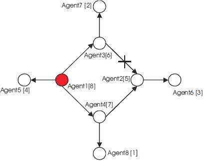
Figure 2 Generated Tree Structure by Application of Spanning Tree Algorithm
In the Figure 2, the numbers in the tags represent the corresponding UIDs of the agents. The target is to break this mesh structure into a tree structure. Therefore binary spanning tree algorithm as shown in Figure 3 is applied. Agent 1 here is chosen as root as it has got the highest UID. Agent 1 sends its UID to Agents 5, 3 and 7(neighboring agents). Since their UIDs are small when compared to Agent1, 1 becomes parent agent to them. Next Agent 4 sends its UID to Agents 2 and 8. Again their UIDs are small compared to Agent 4 hence they become children agents to 4. Then Agent 3 sends its UID to Agents 2 and 7. Now, if you observe Agent 2 is already a child to Agent 4, hence, Agent 3 cannot become its parent agent as per the principle and therefore the crossover. Next, Agent 2 sends its UID to Agent 6 and since the UID of Agent 6 is small in comparison to Agent 2, it becomes a child agent to 2. We can observe that the agents 5, 6, 7 and 8 have no children and therefore become the leaf agents of the tree formed. There is a confirmation check upstream from agents 5, 6, 7 and 8 to 1 and downstream from 1 to 5, 6, 7 and 8 and then tree formed is complete.
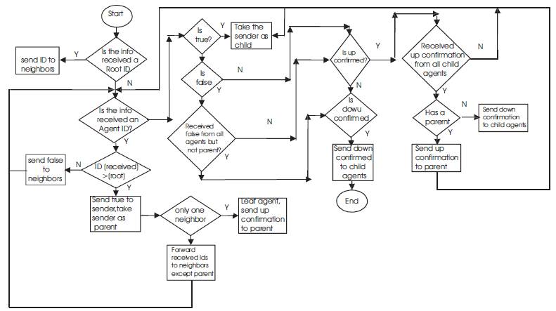
Figure 3. Flowchart showing the Binary Spanning Tree Algorithm
Gt1, GT2, GT3 shown in the Figure 4 indicate the generator transformer sets in the shipboard power system. GT1 is the main generator transformer set; GT2 is auxiliary generator transformer set while GT3 is emergency generator transformer set which serves the vital loads.
Assume that the rating power of GT1, GT2 and GT3 are 175 kW, 125 kW and 60 kW respectively. The rating power of the loads L1, L2, L3, L4, L5 and L6 are 40 kW, 50kW, 35 kW, 40 kW, 35 kW and 40 kW respectively, numbered according their priority. The rating power of the loads L7 and L8 are 15 kW and 25 kW respectively which are considered to be vital loads.
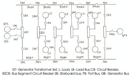
Figure 4. Shipboard Power System for reconfiguration illustration
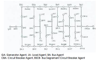
Figure 5. Multi Agent System associated with the Shipboard Power System
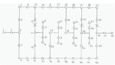
Figure 6. Representation of the agents with their UID's
The Figure 5 shows the MAS associated to SPS after applying binary spanning tree algorithm. The cross marks in the Figure 6 shows the links removed.
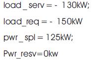
Case1:Load Restoration - GT1 is in operation: In this case, let us assume that the loads L1, L2, L7, and L8 are supplied by the power system and loads L3, L4, L5, and L6 are not supplied by the power system. When the tree structure is generated in the MAS, the leaf agents update the variables load _ serv, load _ req, pwr_ spl, and pwr _ resv . Then the leaf agents send upstream message to the parent agents. The upstream message includes the variables load_ serv, load_req, pwr_spl, and pwr _ resv. When an agent receives upstream message from its load agents, it updates its load _ serv, load _req, pwr_spl, and pwr _ resv. When an agent receives upstream messages from all its children agents, it sends an upstream message to its parent agent. When the root agent GA1 receives the upstream message from CBA1, it updates its variables load _ serv , load_req ,pwr_spl , and pwr _ resv . In this case, the updated variables load _ serv, load _req, pwr_spl , and pwr _ resv of
GA1 is shown as follows:
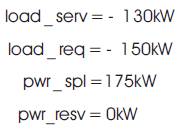
In this case,
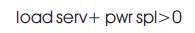

This shows that, some loads can be restored in the SPS based on the priorities of the loads. Load_serv+ pwr_spl=45 kW, the root agent GA1 generates a downstream message ("restore", 45 kW) and sends the message to the children agents. When an agent receives the downstream message from its parent agent, it forwards the message to its children agents. That's how the load L3 is restored power while L4, L5 and L6 are still left unsupplied.
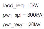
Case 2: Load Shedding - GT2 is in operation: In this case the loads L3, L4, L6 and L7 are supplied and loads L1, L2, L5 and L8 are not supplied by the power system. During the operation, the load L8 (vital) needs to be connected into the SPS. So the agent CBA18 closes the circuit breaker CB18 and connects the load L8 into the SPS. Then the upstream message in the power system will be updated.
In this case, when the root agent GA1 receives the upstream message from CBA1, it updates its variables load _ serv , load_req, pwr_spl , and pwr _ resv . The updated variables load _ serv, load _req, pwr_spl , and pwr _ resv of GA1 is shown as follows:
In this case:

Accordingly, the root agent generates a downstream message ("shed", -5 kW) and sends the message to the children agents. When an agent receives the downstream message from its parent agent, it forwards the message to its children agents. In this case, L8 is supplied power while L6 is out of operation
Case 3: All loads are served - GT1 and GT2 in operation: When GT1 and GT2 share the total system load. The updated variables load _ serv, load _req, pwr_spl , and pwr _ resv of GA1 is shown as follows:

Case 4: All vital loads are served - GT3 is in operation: The updated variables load _ serv, load _req, pwr_spl , and pwr _ resv of GA3 is shown as follows:
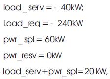
the root agent GA3 generates a downstream message ("restore", 20 kW) and sends the message to the children agents. When an agent receives the downstream message from its parent agent, it forwards the message to its children agents. But this power being insufficient to serve any load, service is not restored. Table 1 shows the circuit breaker status before reconfiguration. Table 2 shows the circuit breaker status after reconfiguration. Table 3 clearly shows the loads being served in each case. Figure 7 clearly depicts that vital loads have always been served as the first priority even under adverse conditions. Case 1 and Case 2 also show up the reconfiguration according to the priority basis thereby maximizing the service restoration.
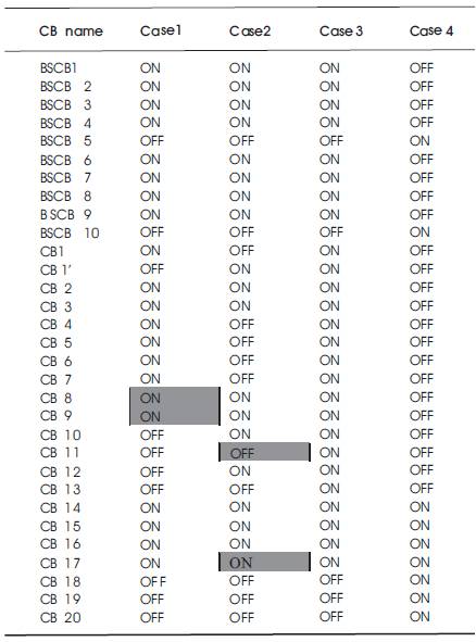
Table 1. Circuit Breaker Status before reconfiguration
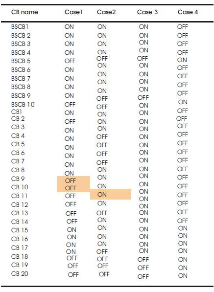
Table 2. Circuit Breaker Status after reconfiguration
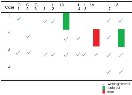
Table 3. load served in each case
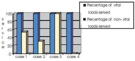
Figure 7. Percentage of loads served in each case
The new approach developed guarantees a quality solution with more ease and flexibility, taking care of each and every section in the system, is applicable to any shipboard power system. It discusses about the problems due to centralized approach and presents a completely decentralized approach for shipboard power system reconfiguration. It also provides a solution for redundant information accumulation problem that occurs in the decentralized reconfiguration of mesh structured SPS. The contribution of this work includes: designing a Multi Agent System based reconfiguration structure, an algorithm that can break an arbitrary mesh structured Multi Agent System into tree structure to avoid redundant information accumulation problem and developing a completely decentralized reconfiguration methodology that can be applied to SPS of any topology. The objective of faster service restoration is achieved as the communication in the decentralized method takes place in a lesser bandwidth.
Agent: An agent is an imaginary entity capable of executing a specified function within its vicinity.
AS: Multi Agent System, a system composed of agents collectively capable of achieving certain specified goal.
UID: Unique Identifier of the agent, representing the power capacity of the corresponding electric component in the power system.
Root: An agent with the highest UID having all its neighboring agents as its children agents.
Leaf: An agent with no children agents or the one which has its neighboring agent as its parent agent.
RIA: Redundant Information Accumulation abbreviated as RIA is a looping problem that occurs in MAS due to its restricted communication with the neighboring agents.